
What Causes a Slurry Pump to Clog During Operation?
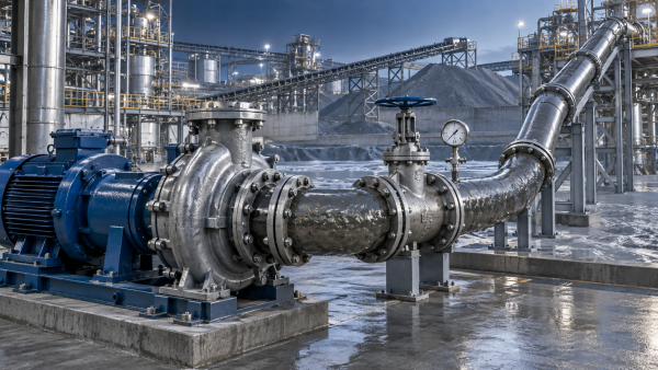
A slurry pump usually clogs because the material reaching the impeller or suction line is no longer moving as the pump and piping system were designed to handle it. The immediate blockage may appear at the suction inlet, impeller eye, throatbush, discharge passage, or a downstream restriction, but the underlying cause often begins earlier: solids are too large, the slurry is too dense or settles in the line, the pump is operating too far from its intended duty point, or worn components have changed the internal flow path.
Clogging is rarely a random event. Pressure fluctuations, falling flow, rising motor load, vibration, repeated seal leakage, and frequent priming problems often appear before a complete blockage. The location and timing of these symptoms help separate a true solids obstruction from air ingress, wear, cavitation, or a piping-system problem that produces similar operating behavior.
Oversized solids and irregular debris
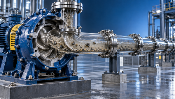
The most direct cause of a blockage is a solid particle that cannot pass through the pump's free-passage size. Slurry pumps are often selected according to nominal pipe diameter or required flow, yet neither value confirms that the largest particles can pass through the impeller and casing. The controlling dimension is the smallest effective passage inside the wet end, which can be at the impeller eye, between impeller vanes, through an expeller arrangement, or near the discharge side of the casing.
Screen opening size should not be confused with actual particle size. Long, flat, fibrous, or flexible material can pass a screen in one orientation and then bridge across a narrower pump passage. Examples include strips of rubber, plastic film, wood fragments, wire, textile material, packaging debris, and scale that has detached from a tank or pipe wall. A hard particle smaller than the nominal passage can also lodge when it combines with other material and creates a bridge.
Particle shape matters as much as maximum size. Rounded mineral particles tend to travel differently from sharp aggregate, flaky solids, drill cuttings, fibers, or mixed process waste. A pump that transfers screened sand without difficulty may clog when the same line receives occasional oversize stones or elongated contamination. This is why a brief inspection of recovered blockage material is more useful than assuming that all feed solids behave alike.
Wear changes the situation further. Enlarged clearances may seem as though they should improve solids passage, but severe wear can reduce the pump's ability to maintain stable velocity and pressure. Broken or heavily eroded vane edges can create recirculation zones where coarse solids accumulate. A damaged impeller may also catch stringy material more easily than a smooth, intact component.
Settling before the slurry reaches the pump
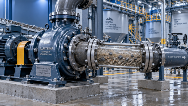
A pump cannot clear solids that have already formed a compact deposit in the suction pipe. Settlement is especially common where velocity is low, where the suction run is long, or where the line includes unnecessary high points, dead legs, abrupt enlargements, and poorly supported sections. Coarse or high-density particles fall out of suspension first. Once a bed develops, the remaining open area becomes smaller, local velocity rises, and the deposit can grow quickly into a restriction.
Intermittent operation makes this problem more likely. During a shutdown, solids settle in low points, suction strainers, valves, and horizontal pipe runs. Restarting at reduced speed may move liquid around the deposit without providing enough force to re-suspend it. The pump then receives a changing mixture: thin liquid at first, followed by a dense plug or a surge of coarse solids. That surge can overload the impeller passage even when average process density appears acceptable.
Low suction velocity is not the only concern. Excessively high velocity can accelerate abrasion, especially with angular mineral slurries, and can create unnecessary friction loss. The correct range depends on particle size, density, concentration, pipe diameter, and whether the solids settle readily. The practical requirement is stable transport velocity through every section of the suction and discharge system, not simply a high velocity reading at one convenient location.
Tank geometry influences suction conditions as well. Settling pockets near the tank outlet, inadequate agitation, a suction nozzle positioned too close to the floor, or a vortexing free surface can send non-uniform slurry into the pump. A suction inlet placed above a settled layer may draw mostly liquid for part of a cycle and then suddenly pull in accumulated solids as the level drops. This often looks like an unpredictable pump blockage, although the source is poor solids presentation at the tank.
Slurry concentration changes the flow regime
A slurry that becomes too concentrated does not always produce a gradual reduction in performance. Its apparent viscosity rises, solids interact more strongly, and the mixture can resist acceleration through bends and narrow pump passages. Fine particles may form a thick, paste-like mass even when there are no oversized solids. In this condition, the pump may continue to rotate normally while flow falls sharply because the slurry is no longer moving through the system as a freely flowing suspension.
Density alone can be misleading. Two slurries with similar density can behave very differently if one contains coarse, dense particles and the other contains a large proportion of fine clay, fines, or fibrous material. Particle size distribution, solids concentration by volume, liquid chemistry, temperature, and entrained air all affect how readily the material flows. A density increase caused by coarse solids requires a different response from a density increase caused by fine cohesive solids.
Flocculation, crystallization, precipitation, and chemical reaction can also turn a manageable slurry into a clogging material. If a process change alters pH, temperature, reagent dosage, or residence time, particles may agglomerate before reaching the pump. The resulting clusters may be soft at first but become compacted in the impeller eye or a valve. Flushing with clear liquid after shutdown may prevent deposits from hardening, but it will not solve a recurring upstream condition that creates agglomerates during normal operation.
Operating too far from the pump's intended duty point
A slurry pump needs enough flow through its wet end to keep solids moving and to limit internal recirculation. When discharge flow is restricted by a closed valve, blocked line, incorrectly positioned valve, fouled cyclone, undersized downstream equipment, or a process change, the pump can operate at low flow. At very low flow, liquid recirculates inside the casing and around the impeller eye. Coarse particles are more likely to drop out of the main stream and collect in these disturbed regions.
Running at low speed can produce a similar result. Variable-speed control is useful when the pump curve, slurry characteristics, and pipeline requirement are considered together. Reducing speed reduces head and flow, but it also reduces line velocity. A speed that is suitable for water testing may be inadequate once solids enter the system. Conversely, increasing speed to clear a suspected restriction can raise wear, suction demand, and power draw without moving a fully settled plug.
Repeated cycling between high and low flow is another source of blockage. Each low-flow period allows solids to settle or recirculate. The next high-flow period dislodges material unevenly, sending slugs through the pump. A stable operating point is generally easier on the pump than frequent swings around the low-flow region.
Suction-side restrictions and air entry
A blocked suction strainer, collapsed flexible hose, partially closed isolation valve, or undersized suction line can starve the pump. Starvation does not always create a solid plug inside the pump; instead, it reduces inlet pressure and disrupts the slurry stream. Solids then separate from the liquid or enter the impeller unevenly. The resulting vibration and loss of flow are sometimes labeled as clogging even though the first fault is a suction restriction.
Air leaks create a comparable pattern. A leaking flange gasket, worn mechanical seal arrangement, loose suction connection, damaged hose, or vortex at the sump surface allows air into the suction stream. Entrained air lowers the effective pumping performance and can cause intermittent loss of prime. Fine slurry may froth, while heavier particles fall out of suspension. A pump that appears blocked for a few seconds and then recovers repeatedly may be handling air pockets rather than a fixed mass of solids.
Suction piping should be as direct as the installation permits. Long horizontal sections, tightly spaced elbows near the inlet, and sudden diameter changes increase uneven flow into the impeller eye. The goal is not merely to connect the pump to the source; the suction arrangement must deliver a uniform slurry stream with sufficient available inlet pressure. When a new blockage follows a piping modification, the altered suction geometry deserves as much attention as the pump itself.
Wear, clearance loss, and damaged internal parts
Slurry pump performance changes as liners, impellers, throatbushes, and side clearances wear. Abrasive slurry removes material from areas that shape the flow path. As internal leakage increases, the pump recirculates more slurry instead of producing useful head and flow. Lower system velocity encourages settlement in the line, and internal recirculation can retain solids near the impeller. The visible blockage may therefore be a consequence of wear rather than the original failure.
Clearance adjustment requires care. On pumps designed for adjustable impeller clearance, excessive clearance lowers hydraulic efficiency and promotes recirculation. Clearance set too tightly can cause rubbing, heat, accelerated wear, or mechanical interference when solids enter the gap. The correct setting follows the pump design and wear condition; copying a setting from a different pump or applying a water-service practice can create new problems.
Rubber liners and elastomeric components deserve separate attention. They resist certain fine, abrasive slurries well, but can swell, soften, tear, or delaminate when exposed to incompatible chemicals or high temperature. A detached liner section can obstruct a passage directly. Hard metal components resist deformation but may erode into rough profiles or crack under impact from large solids. Inspection should include both wear quantity and wear pattern, because a localized abnormal pattern often points to off-design flow or uneven solids entry.
Distinguishing a blockage from cavitation
Cavitation and clogging can both cause noise, vibration, reduced flow, and accelerated damage. Cavitation occurs when local pressure falls enough for vapor bubbles to form and collapse; it is commonly linked to inadequate suction conditions, excessive suction lift, high slurry temperature, or excessive pump speed. A clog is a physical restriction or a loss of solids transport. The two conditions can occur together, especially when a restricted suction line lowers inlet pressure.
A pump suffering mainly from cavitation often produces a harsh, irregular sound and shows pitting or erosive damage in characteristic high-velocity zones. A blockage more often produces a sustained flow reduction, abnormal pressure difference across a known restriction, or recovered debris during dismantling. Diagnosis should use the full pattern: suction pressure, discharge pressure, flow trend, motor load, tank level behavior, and the condition of strainers and piping. Replacing an impeller without identifying the system condition that caused the symptom often leads to a repeat failure.
Where blockages commonly form
The pump itself is not always the blocked component. Low points in discharge piping, reducers, control valves, non-return valves, dead-ended branches, slurry meters, cyclone feeds, and poorly flushed seal-water interfaces can collect solids. A partially blocked discharge line increases system resistance and shifts the pump toward lower flow, which then increases the chance of solids settling elsewhere. This feedback can make a localized restriction look like a general pump-capacity problem.
Bends require particular attention. A long-radius bend with adequate velocity handles abrasive slurry more predictably than a sharp bend where particles strike the outer wall, lose momentum, and build a deposit. Vertical runs may remain clear while adjacent horizontal runs settle. A line that was satisfactory for a dilute commissioning fluid may behave differently once the process reaches its normal solids content.
Responding without worsening the obstruction
When flow drops unexpectedly, forcing the pump to continue at high load can compact material against the impeller, seal areas, or pipe restriction. The appropriate response depends on plant procedures and the equipment arrangement, but the mechanical objective is to avoid grinding a partial obstruction into a tighter plug or running dry after the suction collapses. Pressure and power trends should be captured before conditions are changed, since these readings often disappear once the line is flushed or dismantled.
After isolation and safe depressurization, inspect from the source toward the discharge path rather than assuming the impeller is the first location to open. Confirm tank agitation and liquid level, suction valve position, strainer condition, hose integrity, suction leaks, and obvious pipe settlement. If the pump is opened, record the material found and its location. Fine compacted solids point toward concentration, chemistry, or low-velocity issues; fibrous or irregular debris points toward screening and feed contamination; localized metal or liner damage suggests a mechanical cause that will persist after cleaning.
A durable correction matches the cause. It may involve removing oversize material upstream, changing the screen or grinder arrangement, restoring agitation, maintaining transport velocity, revising a suction line, correcting an operating point, or replacing worn wet-end parts. Cleaning a clogged slurry pump restores flow for the moment. Preventing the next blockage requires identifying why the slurry lost a clear, stable path through the system.
Related Information
 Sep 29, 2026
What causes slurry pump failures in flue gas desulfurization systems
Flue Gas Desulfurization Systems: discover the main causes of slurry pump failures, from cavitation and abrasion to seal leaks, corrosion, and unstable operation.- Sep 29, 2026
What Causes a Slurry Pump to Clog During Operation?
What causes a slurry pump to clog during operation? Explore key causes, warning signs, and proven solutions to prevent downtime, wear, and costly flow disruptions. - Sep 29, 2026
Can a Slurry Pump Handle High Solids Concentrations?
Can a slurry pump handle high solids concentration? Discover how pump design, particle size, materials, and pipeline conditions ensure reliable, efficient slurry handling. - Sep 22, 2026
How Does an OEM Slurry Pump Custom Order Process Work?
Delin OEM slurry pump custom order process: learn how duty analysis, material selection, seal options, testing, and commissioning create reliable pumps for demanding slurry applications.
Get a Quote
Please leave your information and email address, and we will contact you as soon as possible.