
River sediment removal rarely fails because a pump is simply “too small.” More often, the selected unit matches a nominal flow requirement but cannot tolerate the actual material arriving at the intake: changing sand content, occasional gravel, fibrous debris, shallow water, a long discharge line, or abrasive slurry running for extended shifts. The result can be low production, frequent blockages, rapid wear, or a pump that appears adequate on paper but operates far from its efficient range.
To select a dredging pump for river sediment removal project, begin with the sediment and the hydraulic system rather than pump size alone. Define the particle-size range, slurry concentration, required solids production, total dynamic head, discharge distance, and installation method. Then choose a pump whose flow, head, passage size, materials, and drive arrangement suit the worst credible operating condition—not only the average condition measured on a calm day.
Start with the material that must be moved
“River sediment” can describe very different materials. Fine silt behaves differently from sharp sand; compacted deposits need a different approach from loose bed material; and a riverbed that appears sandy may contain stones, roots, litter, shell fragments, or construction debris. The pump selection changes substantially when the solids are larger, denser, more abrasive, or less uniform.
Before choosing a model, obtain representative information from sampling, survey records, test dredging, or site observations. A useful description should include particle-size distribution, maximum expected particle size, solids density, likely debris, and whether the material is loose, layered, or compacted. If exact laboratory data are unavailable, do not replace it with a single assumption such as “mostly sand.” Define a reasonable range and size the equipment around the more difficult end of that range.
The maximum particle size is particularly important. A pump may transfer a large volume of fine material well but repeatedly clog when isolated oversize objects enter the suction. The limiting dimension is not only the suction hose diameter. It also includes the impeller eye, internal passages, and any restriction in the line. Confirm the manufacturer’s solids-handling guidance for the actual pump configuration, rather than assuming that a wide suction pipe guarantees free passage.
Convert the removal target into solids capacity
A project requirement expressed as “remove a certain amount of sediment” must be translated into a pump duty. Pump flow is generally stated as slurry volume per unit time, while site targets may be based on in-situ volume, dry solids mass, or trucked material. These are not interchangeable because dredged slurry contains water, and the amount of entrained water can vary widely with the excavation method and sediment type.
First establish the practical production objective: how much in-situ material must be removed during each operating period? Then estimate an achievable slurry solids concentration. A pump that moves a high liquid flow but carries little solids may produce an impressive flow reading while delivering poor removal output. Conversely, pushing concentration too high can increase line friction, overload the drive, cause unstable suction, and accelerate wear.
For a preliminary decision, separate two questions:
- What slurry flow is needed to keep solids suspended and travel through the discharge line?
- At that flow, what solids concentration is required to meet the planned removal rate without exceeding the pump and engine limits?
The answer often requires iteration. Higher concentration improves solids yield per unit of water, but it raises slurry density and resistance. Higher flow can improve transport velocity, but it raises power demand and may create unnecessary erosion in pipes and bends. A suitable duty point balances these effects rather than maximizing one of them.
Calculate total dynamic head from the full discharge route
Flow and head must be considered together. A pump selected only by capacity can disappoint when the discharge pipeline is long, elevated, or routed through multiple bends. Total dynamic head is the combined resistance the pump must overcome at the required flow. It includes static lift, friction loss in straight pipe, losses through bends and valves, entrance and exit losses, and the added resistance associated with transporting a slurry rather than clean water.
Static lift is easy to see when material is pumped from a riverbed to an elevated disposal area, but it is not the only factor. Long horizontal lines can create substantial friction loss, especially when pipe diameter is too small or the system includes many fittings. Flexible hose, worn pipe, abrupt reducers, and partially closed valves can further alter the real duty.
Use the intended pipeline diameter and total length in the calculation, including floating line, shore line, vertical risers, and all planned fittings. Also assess whether the route may change during the job. A pump that works adequately while discharging nearby may no longer meet the duty once the disposal point moves farther away. Where discharge distance will increase in stages, select for the more demanding stage or plan a booster pump arrangement from the outset.
Do not use clean-water curves without slurry correction
Pump performance curves are commonly published for clean water. Sediment reduces hydraulic performance because the mixture is denser and particles consume energy through friction, collision, and settling effects. The degree of reduction depends on solids size, density, concentration, and pump design. A duty point that appears safely within a water-based curve may be marginal once abrasive sand or gravel is introduced.
Ask for performance information or engineering guidance applicable to the expected slurry. The calculation should also verify absorbed power, not only head and flow. A pump may reach the required head but exceed available engine or motor power under high-density slurry conditions. Leaving a realistic power margin is preferable to operating continuously at the limit, particularly where material consistency changes during excavation.
Keep transport velocity above the settling risk
Once solids enter the pipeline, the line must carry them without allowing a bed to form. If velocity falls below the level needed for the particular sediment, heavier particles settle in low sections, bends, and transitions. The restriction increases resistance, which reduces flow further and can lead to a full blockage. Restarting after a settled line may require flushing, reversing flow where possible, or dismantling pipe sections.
There is also an upper boundary. Excess velocity wastes power and increases wear, especially at elbows, reducers, valves, and the outer radius of bends. The objective is a stable transport window: high enough to prevent deposition, but not so high that the system consumes unnecessary energy and sacrifices pipe life.
Pipe diameter therefore cannot be selected independently from pump flow. An oversized line may lower velocity below the safe transport range; an undersized line raises friction and wear. For variable operating conditions, operators need a practical way to observe performance, such as pressure readings, flow indication, engine load, and visual inspection of discharge consistency. These operating signals can reveal settling or dilution before a blockage becomes severe.
Choose the right dredging arrangement before finalizing the pump
The same hydraulic pump can perform very differently depending on how sediment is fed into it. The installation should match water depth, access limitations, required digging action, and material condition.
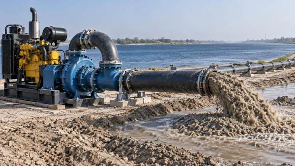
A submersible dredge pump places the wet end near the material and can be useful where portable deployment, restricted access, or lower suction lift is important. Agitators or cutters may help disturb settled sediment, but they also increase wear exposure and require adequate power. A floating dredge arrangement can work well for broad, accessible reaches where the suction head can be positioned accurately. A land-based or trailer-mounted pump may be suitable when it can maintain a reliable flooded suction or when the excavation method feeds material to the intake.
Suction conditions deserve careful attention. Centrifugal dredging pumps do not perform well when air enters the suction line, the suction lift is excessive, or intake conditions create vortices. Cavitation, unstable flow, and loss of prime may follow. Keep the suction route as short and direct as practical, avoid unnecessary high points, provide sufficient submergence, and ensure the intake position does not pull excessive air from the surface.
Where sediment is compacted, a larger pump alone may not improve output. The limiting factor may be the ability to loosen and entrain material. A cutter head, excavator-assisted feeding method, jetting arrangement, or mechanical pre-loosening method may be needed, depending on site conditions. Pump selection should reflect the expected feed method because the feed method determines concentration, particle size, and material consistency at the pump inlet.
Specify wear resistance as an operating-cost decision
Abrasive sediment attacks impellers, liners, casings, throatbushes, and suction-side components. Sharp quartz-rich sand can be especially demanding. Selecting highly wear-resistant materials may increase initial cost, but choosing a lightly built pump for a long abrasive duty can lead to frequent shutdowns, declining hydraulic performance, and difficult maintenance scheduling.
Wear parts should be considered alongside replacement access. Ask how liners and impellers are inspected, whether the pump can be opened without removing major pipework, what lifting access is required, and which parts should be held on site. A remote river location with limited service access often justifies a design that is easier to maintain, even if another option offers a slightly lower purchase price.
Wear also changes the duty point over time. As clearances increase and impeller geometry degrades, head and efficiency can fall. A system designed with no margin may fail to meet discharge requirements well before a component reaches complete mechanical failure. Monitoring suction and discharge pressure, power draw, and production rate helps identify this gradual loss.
Match the drive and controls to variable river conditions
Diesel, electric, hydraulic, and mechanical drive arrangements each have practical limits. The correct choice depends on available power, mobility needs, fuel handling, noise restrictions, cable access, and whether speed control is required. The drive must provide enough continuous power for the expected slurry duty, with reserve for denser material or temporary increases in line resistance.
Variable speed is valuable when river conditions change. Reducing speed can prevent excessive pipe velocity during light slurry operation; increasing speed may restore transport velocity when concentration rises or discharge distance grows. Speed adjustment is not a substitute for correct sizing, however. Running continuously at extreme low or high speed can move the pump away from its preferred operating region.
Controls should support decisions in the field. At minimum, operators benefit from clear engine or motor load indication, discharge pressure monitoring, temperature and lubrication alarms where applicable, and a defined shutdown procedure for blocked or unstable operation. A sudden pressure increase can indicate downstream restriction; falling pressure with reduced load may point to air ingress, loss of feed, or severe wear. These signals are more useful when baseline readings are recorded after commissioning.
Questions to resolve before issuing a pump specification
A workable specification is more than a requested flow rate. It should state the expected sediment range, maximum particle size, slurry concentration range, target solids output, pipeline profile, total discharge distance, static lift, pipe diameter, number of major fittings, water depth, installation arrangement, available power source, and expected operating hours. It should also identify debris risk, required mobility, access for maintenance, and whether the disposal route will change.
Where these details are uncertain, identify the uncertainty explicitly. For example, an unknown gravel fraction or an unconfirmed final discharge elevation can have more effect on selection than small differences between pump models. Field sampling and a simple pipeline survey may prevent a costly mismatch later.
The final selection should place the anticipated slurry duty near the pump’s stable, efficient operating range while preserving margin for wear, changing discharge distance, and realistic sediment variability. That approach produces a more reliable river sediment removal system than selecting the largest available pump or relying on a clean-water flow number alone.
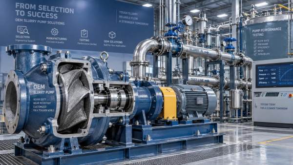
 Sep 22, 2026How Does an OEM Slurry Pump Custom Order Process Work?Delin OEM slurry pump custom order process: learn how duty analysis, material selection, seal options, testing, and commissioning create reliable pumps for demanding slurry applications.
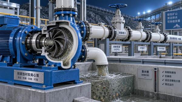
- Sep 22, 2026How to Choose a Corrosion-Resistant Pump for Acid Mine DrainageCorrosion resistant pump for acid mine drainage: learn how to match materials, seals, hydraulics, and solids handling for longer service life.
- Sep 23, 2026How to Select a Dredging Pump for River Sediment Removal ProjectsSelect the right dredging pump for river sediment removal project with expert guidance on slurry flow, head, wear resistance, solids handling, and reliable performance.
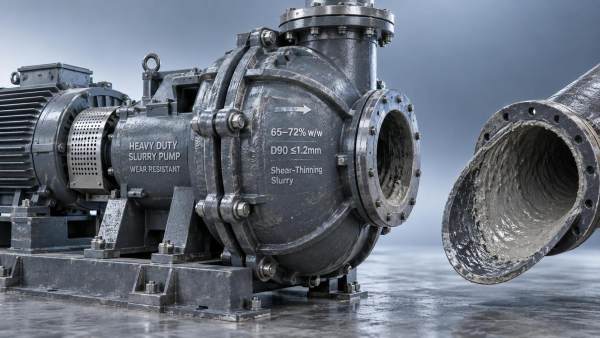
- Sep 20, 2026Corrosion Resistant Pumps: A Complete Selection Guide for Chemical, Mining, and Power Generation ApplicationsLearn how to select corrosion resistant pumps for chemical processing, mining, and power generation. Compare stainless steel, duplex, high-chromium alloy, rubber-lined materials, key specifications, and sealing options for corrosive and abrasive slurry service.
Get a Quote
Please leave your information and email address, and we will contact you as soon as possible.