
How to Choose a Foam Pump for a Mineral Flotation Circuit
Start with the froth, not the pump catalogue
A foam pump for a mineral flotation circuit should be selected around the froth condition at the duty point, then checked against the hydraulic and mechanical demands of the circuit. A pump that appears adequate on flow and head can still perform poorly when the feed contains a high air fraction, unstable froth, abrasive mineral solids, or wide swings in density. The usual result is not simply lower pump efficiency. It can be surging discharge flow, loss of suction, excessive vibration, accelerated wet-end wear, and an operating circuit that becomes difficult to control.
The first question is therefore not “Which pump size matches the pipe?” It is: “What is actually arriving at the pump inlet, and how consistently does it arrive?” In flotation service, the answer can change with ore type, reagent dosing, cell air rate, water balance, and upstream level control. A sound selection process treats the foam pump as part of the flotation circuit, rather than as an isolated slurry-transfer item.
For many duties, a purpose-designed vertical froth pump is the practical starting point. Its tank geometry, inlet arrangement, impeller design, and induced vortex are intended to separate some entrained air before the slurry enters the impeller eye. That does not make every vertical froth pump suitable for every circuit. Particularly variable, highly viscous, or high-head duties may require a more detailed comparison with horizontal slurry pumps, booster arrangements, or changes to the feed tank and piping layout.
Characterize the feed in operating terms
Process data for a flotation pump is often incomplete because the slurry is difficult to sample and the air content is not steady. Even so, a selection should not proceed on nominal flow alone. The pump supplier or engineering team needs a realistic operating envelope, including normal, minimum, and maximum conditions.
The most important feed characteristics are usually:
- Solids concentration and density: These affect power draw, hydraulic losses, wear rate, and the way bubbles move through the slurry. A light froth overflowing from one bank may behave very differently from a dense scavenger concentrate stream.
- Particle size and mineral abrasiveness: Fine particles do not automatically mean low wear. Hard, sharp mineral particles can erode impellers, liners, throats, and discharge components even where the top size is modest.
- Air or gas entrainment: The amount matters, but the pattern matters too. Large bubbles, finely dispersed air, and persistent foam each affect pump inlet behavior differently.
- Froth stability: Stable froth can accumulate in launders and feed boxes, while collapsing froth can produce sudden changes in density and level. Reagent chemistry and mineralogy influence this behavior.
- Temperature, pH, chloride content, and chemical exposure: These influence elastomer compatibility, corrosion risk, seal selection, and material choice for metal components.
- Flow variability: A pump that operates close to its preferred region at the average duty may become unreliable if routine process changes push it far to either side of that point.
It is also useful to identify where the pump sits in the circuit. A rougher concentrate transfer duty, a cleaner scavenger stream, and a tailings-related froth duty may all be called “flotation slurry,” yet their operating conditions can be materially different. The upstream cell arrangement, launder configuration, sump volume, and density-control method should be reviewed before finalizing equipment.
Why air handling changes the selection
Entrained air is the feature that separates froth pumping from conventional slurry pumping. Air reduces the effective density of the mixture and can interfere with stable liquid flow into the impeller. If a conventional pump is fed with heavily aerated froth, the impeller may not receive a continuous slurry stream. Capacity becomes erratic, pressure fluctuates, and the pump can appear to be oversized or undersized depending on the moment of observation.
A vertical froth pump commonly uses a large tank and a vortex created by the impeller to encourage air release before pumping. The design supports a more uniform slurry feed at the impeller eye. The pump does not eliminate every air-related problem. Excessive air, inadequate tank residence time, a restricted feed path, or poor level control can still overwhelm the system.
The pump feed tank deserves the same attention as the pump itself. A tank that is too small may allow froth to pass through before air can disengage. An inlet aimed directly at the suction zone can pull large pockets of air toward the impeller. Poorly arranged overflow paths can create intermittent starvation even when the average liquid level looks acceptable. In many problem installations, improving the tank geometry, inlet calming, or level-control response does more for stable pumping than changing the impeller diameter.
Do not assume that a larger pump is the cure for severe aeration. A larger impeller can increase the circulation and turbulence within the tank without creating a stable suction condition. It may also consume more power while still delivering inconsistent flow. The better response is to determine whether the air burden should be managed upstream, within the froth tank, or by changing the pump configuration.
Build the duty point from the system, not a single head number
Flow rate and total dynamic head remain essential, but they need to be developed as a range. For a mineral flotation circuit, the design should account for static lift, discharge pressure requirements, pipe friction, fittings, control valves, cyclone or downstream equipment losses, and the effect of slurry properties on the system curve. The resulting duty should be checked at expected slurry density and, where possible, at less favorable operating conditions.
There are two common errors. The first is using water-based pump curves without properly applying slurry corrections. The second is selecting exactly at the calculated normal duty, leaving no margin for wear, production changes, or higher-than-expected pipe losses. Both can lead to a pump operating at the edge of its usable range.
Margin should be deliberate, not arbitrary. Too little margin can leave the pump unable to meet the required transfer rate after wet-end wear or a process change. Too much flow margin may force throttling, recirculation, excessive velocity, or operation far from the pump’s best efficiency region. Excessive head margin can also encourage a pump to run at an unnecessarily high speed, increasing wear and power demand.
A practical review should ask the following:
- What flow is required continuously, and what flow occurs only during upset or peak production?
- Does downstream equipment require a minimum pressure, or is the pump simply transferring material to a gravity-fed location?
- How will the system behave as pipework scales, liners wear, or the solids concentration rises?
- Can the pump speed be adjusted through a variable-frequency drive, and is the motor sized for the highest credible absorbed power?
- Will the operating point remain within the manufacturer’s recommended range at both normal and abnormal process conditions?
Variable speed is particularly useful in flotation circuits with changing feed rates or froth characteristics. It gives operators a way to match pump output to tank level and downstream demand without relying entirely on a throttling valve. It should not be treated as a substitute for correct sizing. A poorly selected pump may still be unstable at the speeds where the circuit needs to operate.
Match wet-end materials to wear mechanisms
Froth service often combines abrasive wear with conditions that are less straightforward than a high-density slurry line. The material selection should reflect particle hardness, size distribution, impact velocity, corrosion exposure, and temperature. High-chrome white iron is widely used where abrasive wear dominates, while elastomer linings can be attractive for fine, less sharply abrasive particles and certain chemical environments. Neither option is universally better.
Hard-metal components generally resist cutting and gouging from coarse or aggressive particles. They can be a sensible choice for duties with substantial abrasion and higher operating velocities. Elastomer components may handle fine slurry well, absorb particle impact, and simplify certain maintenance tasks, but they can be damaged by unsuitable oils, solvents, elevated temperatures, or coarse sharp particles. Chemical compatibility must be checked against the actual process environment, including reagents and cleaning practices.
Wear is not limited to the impeller. Throatbushes, liners, suction covers, tank agitator components where fitted, and discharge elbows may govern maintenance intervals. If the pump will be installed where access is difficult, consider how each wear part will be inspected and replaced. A low initial equipment price can be outweighed quickly by long shutdowns, crane access, or frequent replacement of components that are hard to reach.
Where slurry chemistry raises corrosion concerns, material selection should consider corrosion and abrasion together. Corrosion can weaken a surface and accelerate particle erosion; abrasion can remove protective films and expose fresh metal. Choosing a material solely from a hardness value can miss this interaction.
Sealing and shaft arrangement should follow the installation
Vertical froth pumps are often preferred partly because many arrangements avoid the complex mechanical seal system common in horizontal slurry pumps. A cantilevered vertical shaft keeps bearings above the slurry zone and can simplify the wet-end arrangement. This is useful where seal-water supply is unreliable, contamination must be avoided, or maintenance teams want fewer auxiliary systems to manage.
That advantage has limits. Shaft length, bearing spacing, shaft stiffness, and pump speed must suit the duty. A tall installation or a high-speed configuration can increase deflection and bearing loading. Inadequate alignment between the motor and pump drive, poor lubrication practices, or an unsupported discharge pipe can shorten mechanical life even when the wet-end selection is correct.
For horizontal alternatives, seal choice becomes a more central decision. Expeller arrangements, packed glands, and mechanical seals each have operating implications. The choice should be based on leakage tolerance, slurry characteristics, utility availability, environmental requirements, and maintenance capability. A mechanical seal may be appropriate in a controlled application, but it should not be specified simply because it appears more advanced. In abrasive, aerated service, complexity without disciplined maintenance can create an avoidable failure point.
Look beyond the pump curve when comparing suppliers
Two pumps with similar published flow and head ranges may behave differently in a froth circuit because their tank volume, impeller inlet geometry, air-handling arrangement, shaft design, and material options differ. Comparing only the curve and motor power can conceal important differences.
A useful technical comparison should include the complete package: pump, froth tank, motor, drive, baseframe, controls, instrumentation connections, lifting provisions, and access for wear-part replacement. Confirm the proposed tank volume and inlet orientation, rather than assuming they are standard. Ask how the pump is expected to handle the estimated air content, what operating range is recommended, and how the supplier has accounted for slurry corrections.
Spare-parts strategy also deserves an early decision. Critical parts may include impellers, liners, throatbushes, bearings, belts or coupling elements, and instrumentation components. The correct stock level depends on wear severity, delivery lead time, and the consequences of a pump outage. A flotation circuit with no transfer redundancy may justify holding more critical wet-end and drive components than a duty with a standby pump already installed.
Interchangeability can reduce inventory burden, but only where it does not compromise duty fit or material selection. Standardizing every froth duty onto one pump model may look efficient on paper while creating poor operating points in parts of the plant. Standardization works best when the process envelope is genuinely similar.
Plan for the operating problems that reveal a bad fit
A well-selected foam pump should produce a reasonably stable discharge flow and maintain controlled tank levels over expected process variation. When problems arise, the first symptoms are often operational rather than catastrophic: fluctuating pressure, pump noise, repeated level-controller intervention, falling throughput, vibration changes, or unexpectedly rapid wear.
These symptoms should not automatically be attributed to the pump. Check the circuit in sequence: flotation cell discharge behavior, launder restrictions, tank level, air release, inlet blockage, pump speed, discharge valve position, pipework condition, and downstream backpressure. A pump can be blamed for a circuit issue it is only exposing.
The most reliable selection process therefore ends with an operating review, not a purchase order. Define the real feed envelope, model the system resistance, select an air-tolerant configuration appropriate to the froth condition, and make sure materials and maintenance access fit the expected wear environment. When those elements align, the pump becomes a stable part of flotation control instead of a recurring source of lost availability.
Related Information
 Sep 22, 2026
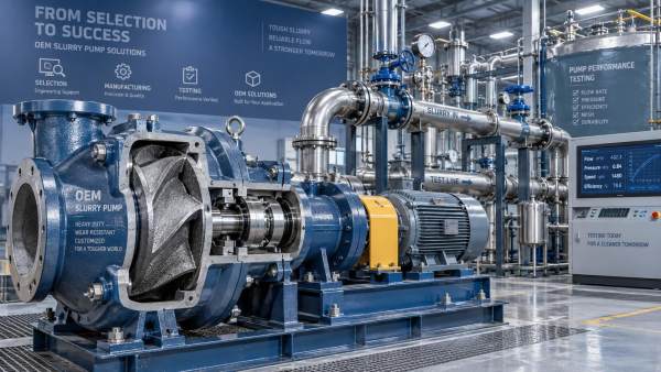
How Does an OEM Slurry Pump Custom Order Process Work?
Delin OEM slurry pump custom order process: learn how duty analysis, material selection, seal options, testing, and commissioning create reliable pumps for demanding slurry applications.- Sep 23, 2026
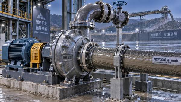
Which Pump Is Suitable for High-Concentration Tailings Disposal?
High concentration slurry pump for tailings disposal: learn how to select a heavy-duty centrifugal pump with wear-resistant materials, reliable sealing, and pipeline-matched performance. - Sep 22, 2026
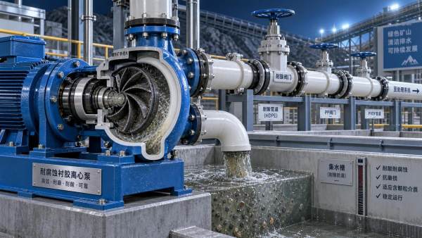
How to Choose a Corrosion-Resistant Pump for Acid Mine Drainage
Corrosion resistant pump for acid mine drainage: learn how to match materials, seals, hydraulics, and solids handling for longer service life. - Sep 23, 2026
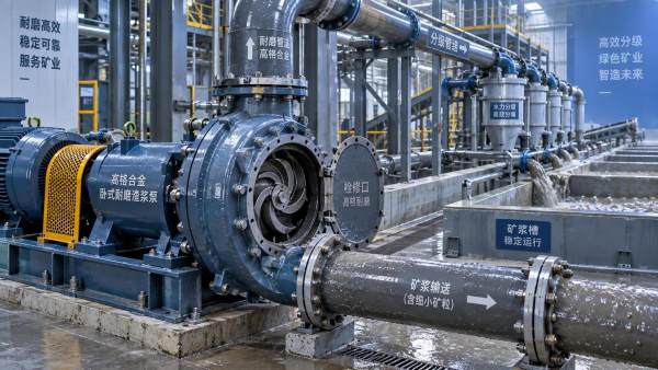
What Should a Mineral Processing Plant Look for in an Abrasive Slurry Pump?
Abrasive slurry pump for mineral processing plant selection: compare slurry properties, pump curves, wear materials, suction design, and maintenance factors for reliable performance.
Get a Quote
Please leave your information and email address, and we will contact you as soon as possible.