
How Do You Maintain a Double-Casing Slurry Pump?
A double-casing slurry pump works under demanding conditions, handling abrasive solids that can accelerate wear and reduce performance.
Effective double casing slurry pump maintenance helps operators identify problems early, protect critical components, and minimize unplanned downtime.
From routine inspections and seal checks to wear-part replacement and correct operating practices, a consistent maintenance plan supports reliable performance and longer equipment life.
This guide explains what to inspect, when to take action, and how to keep your pump operating efficiently.
What Does Effective Slurry Pump Maintenance Involve?
Maintain a double-casing slurry pump by monitoring operating conditions, inspecting seals and bearings, adjusting clearances where permitted, and replacing worn components before they fail.
The most useful warning signs are changes from the pump’s normal baseline: falling flow or discharge pressure, rising vibration, unusual bearing temperatures, and increased leakage.
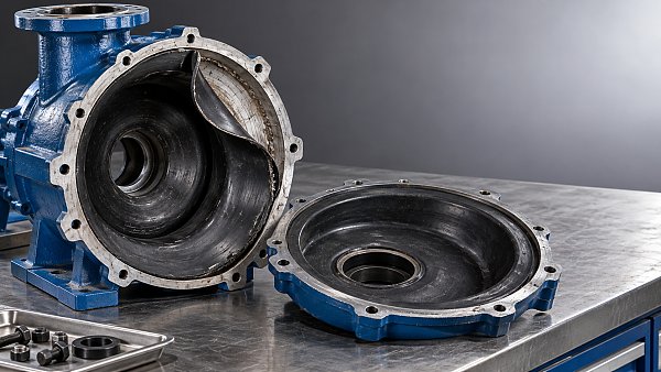
A double-casing design typically uses a replaceable internal wear liner inside an outer casing. The liner protects the casing, but both require inspection.
Maintenance intervals depend on slurry abrasiveness, particle size, operating hours, and pump design. Begin with the manufacturer’s instructions, then adjust using inspection history.
For reliable results, assign responsibility for routine checks, record readings consistently, and establish clear escalation limits before problems interrupt production.
How Often Should You Inspect a Double-Casing Slurry Pump?
Use the following schedule as a starting framework, not a substitute for the equipment manual. Severe applications may require more frequent checks.
- Each operating shift: Check for abnormal noise, vibration, leakage, bearing temperature, seal-water supply, and changes in flow or pressure.
- Weekly: Inspect accessible fasteners, guards, pipe supports, lubrication condition, and visible signs of erosion or corrosion around the pump.
- Monthly: Review operating trends, inspect alignment indicators and coupling condition where safely accessible, and check impeller clearance if the design permits adjustment.
- During planned shutdowns: Inspect internal wear parts, shaft sealing components, bearings, and casing condition according to the manufacturer’s procedures.
- After unusual events: Inspect following dry running, loss of seal water, blockage, sudden vibration, flooding, or operation outside the approved range.
New installations and pumps handling highly abrasive material benefit from closer early monitoring. Initial inspections establish actual wear rates for the specific duty.
Record operating hours rather than relying only on calendar dates. A continuously operated pump accumulates wear much faster than one used intermittently.
Trend readings over time instead of waiting for an obvious failure. A gradual pressure decline combined with increasing power demand can justify investigation.
Set alarm and shutdown thresholds using the manufacturer’s limits, site standards, and baseline data. Avoid applying a generic temperature or vibration limit universally.
What Should Operators Check During Each Shift?
Start with the process readings. Compare flow, suction pressure, discharge pressure, motor current, and speed with normal values at a similar operating duty.
A drop in flow or discharge pressure may indicate wear, blockage, air ingress, insufficient suction supply, or changes in slurry characteristics.
Listen for new grinding, rattling, or intermittent knocking. These symptoms can indicate contact between components, loose parts, cavitation, or solids accumulation.
Observe leakage at the shaft seal and casing joints. Investigate sudden changes promptly, while recognizing that some packed seals require controlled leakage.
Check bearing housing temperature with an installed sensor or an approved measuring method. Rising temperature can signal lubrication problems, misalignment, or bearing damage.
Confirm seal-water pressure and flow where a flushed seal is fitted. Follow the seal supplier’s limits because requirements vary by arrangement and duty.
Look for slurry deposits around the base, joints, and pipework. Deposits can reveal a small leak before it damages surrounding equipment.
Never remove guards, touch rotating components, or open pressurized connections during an operating inspection. Report unsafe conditions and follow site procedures.
How Do You Know When Liners and Impellers Need Replacement?
Replace wear parts based on measured condition, performance trends, and manufacturer limits rather than appearance alone. Plan replacement before wear reaches the outer casing.
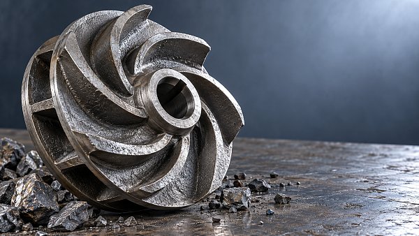
Common indicators include reduced flow at unchanged speed, lower discharge pressure, increased recirculation, unstable operation, or a growing impeller-to-liner clearance.
These symptoms are not conclusive by themselves. Check suction conditions, instrumentation, pipeline restrictions, and slurry properties before attributing the problem to internal wear.
During a shutdown, inspect the impeller, throatbush, frame plate liner insert, and other wetted components applicable to the pump model.
Measure remaining thickness and clearance at the locations specified by the manufacturer. Compare results with rejection limits and previous inspection records.
Inspect the outer casing separately for erosion, cracks, corrosion, and damage at joints or mounting surfaces. Replace or repair it according to approved criteria.
Wear is often uneven. Concentrated damage near the impeller eye, discharge, or liner joints may reveal operating problems that replacement alone will not solve.
Estimate the next replacement date from the observed wear rate, allowing a margin for changing process conditions and parts procurement time.
Can Impeller Clearance Be Adjusted to Restore Performance?
On pumps designed with an adjustable impeller clearance, correcting excessive clearance can recover some performance without immediately replacing the impeller or liner.
Adjustment limits and procedures vary by pump. Some designs require the rotor to be positioned relative to a specific liner face or reference point.
Before adjustment, isolate the equipment, confirm it cannot restart, and follow the manufacturer’s instructions for draining, guarding, and access.
Measure the existing setting and inspect for damage. Make the prescribed adjustment in small increments, then verify that the rotor turns freely as instructed.
Excessively tight clearance can cause rubbing, heat, vibration, and rapid damage. Never use contact during operation as a method for finding the setting.
Clearance adjustment cannot restore missing material or correct severe damage. If the required setting cannot be maintained, inspect and replace affected wear parts.
Record the final setting, operating hours, and subsequent performance. Frequent adjustments over a short interval indicate that replacement or process investigation is needed.
How Should You Maintain Shaft Seals and Bearings?
The correct seal maintenance procedure depends on whether the pump uses gland packing, a mechanical seal, an expeller seal, or another arrangement.
For packed glands, maintain the controlled leakage specified by the manufacturer. Tightening packing until leakage stops can overheat and damage the shaft sleeve.
Adjust gland fasteners evenly and gradually when permitted. Replace packing and inspect the sleeve if leakage remains excessive or adjustment is exhausted.
Mechanical seals require clean, compatible support fluid at the specified pressure and flow when a flush is required. Do not run them dry.
Investigate recurring seal failure for shaft movement, misalignment, contaminated flush fluid, incorrect installation, or operation outside the seal’s pressure and temperature limits.
For bearings, use the lubricant type and quantity specified by the manufacturer. Both insufficient lubrication and overgreasing can raise temperature and shorten bearing life.
Check seals and breathers on bearing housings to limit water and slurry contamination. Milky oil, discolored grease, or metal particles warrants investigation.
After bearing work, verify shaft end play, assembly settings, lubrication, and alignment according to the manual before returning the pump to service.
Which Operating Practices Reduce Wear and Unplanned Downtime?
Keep the pump close to its approved operating range. Prolonged operation far from its best efficiency point can increase recirculation, vibration, and uneven wear.
Maintain adequate suction conditions and prevent the suction line from drawing air. Cavitation or air entrainment can reduce performance and damage components.
Confirm that slurry density, particle size, solids concentration, and temperature remain within the pump and seal design limits. Process changes can alter wear rates significantly.
Avoid running the pump dry or against a closed discharge unless the manufacturer explicitly permits a defined procedure and duration.
Check that suction and discharge piping are supported independently. Pipe strain can distort the casing, affect alignment, and increase seal or bearing loads.
Control speed changes carefully. Increasing speed may increase capacity, but it can also accelerate erosion and raise power requirements beyond the motor’s rating.
When shutdown procedures require flushing, use a compatible fluid and follow site instructions. Prevent solids from settling inside the pump and connected lines.
Coordinate operating changes with maintenance personnel. A new ore source, higher production rate, or altered particle size may require shorter inspection intervals.
What Should You Do Before Opening the Pump?
Only trained personnel should dismantle slurry equipment. Begin with a job-specific risk assessment and the pump manufacturer’s disassembly and lifting instructions.
Stop the pump, isolate all energy sources, and apply the site’s lockout and tagout procedure. Verify zero energy before starting work.
Isolate suction, discharge, seal-water, and other connected services as required. Depressurize, drain, and flush the pump safely before opening any joint.
Account for hazardous slurry, hot surfaces, trapped pressure, and residual material. Use the personal protective equipment specified by the site assessment.
Support heavy casing sections and wear parts with rated lifting equipment. Use designated lifting points and never work beneath a suspended load.
Mark component orientation, retain inspection records, and check replacement parts against the equipment identification. Incorrect liners or seals can prevent proper assembly.
After reassembly, check fasteners, guards, piping, seal supplies, alignment, and free rotation as directed. Restart under controlled conditions and monitor initial readings.
How Can You Troubleshoot Common Pump Problems?
Low flow or pressure: Verify instrument readings and tank level first. Then check for suction restrictions, air ingress, worn hydraulics, or incorrect speed.
High vibration: Check for blockage, cavitation, loose foundations, misalignment, bearing deterioration, and impeller damage. Escalate promptly if readings exceed site limits.
Excessive seal leakage: Confirm the seal type and expected leakage. Check flush supply, gland adjustment, shaft sleeve condition, and shaft movement.
High bearing temperature: Review lubrication quantity and condition, alignment, operating load, and cooling arrangements. Stop the pump when required by established limits.
Frequent liner replacement: Compare actual slurry properties and operating speed with the design duty. Inspect wear patterns and discuss material selection with the supplier.
When multiple symptoms appear together, investigate their timing. A process change followed by declining flow and rising vibration may point to a common cause.
How Do You Build a Practical Maintenance Plan?
Start with the pump model, serial number, operating duty, and manufacturer’s recommended tasks. Add site-specific inspection points based on process risks.
Track operating hours, flow, pressure, vibration, bearing temperature, seal leakage, adjustments, and replacement dates. Consistent records make deterioration easier to recognize.
Keep critical spares available according to failure consequences and supplier lead times. Typical candidates include liners, an impeller, seals, bearings, and required gaskets.
Review maintenance costs alongside production losses, energy consumption, and wear-part life. The lowest-cost component is not always the lowest-cost option over its service life.
After each major inspection or failure, update the schedule and investigate underlying causes. Assign corrective actions so recurring defects do not become routine.
Conclusion
Effective double casing slurry pump maintenance combines shift checks, condition-based wear inspections, correct seal and bearing care, and disciplined operating practices.
Use manufacturer limits and site history to decide when to adjust, repair, or replace components. Early action protects the outer casing and reduces unexpected downtime.
Related Information
 Nov 08, 2026
Why Is My Slurry Pump's Rubber Liner Peeling?
Can sharp particles make your slurry pump's rubber liner peel? Discover the warning signs, other common causes, and practical ways to prevent repeat failures.- Nov 08, 2026
Do High-Chrome Pump Parts Resist Coarse, Sharp Particles?
Will high chrome pump parts resist wear from coarse, sharp particles? Discover when they perform best and how to choose the right alloy for your slurry. - Nov 07, 2026
What Factors Affect FGD Pump Lifecycle Cost?
FGD pump lifecycle cost goes beyond purchase price. Explore how energy, slurry wear, maintenance, spares, and downtime affect your total investment. - Nov 07, 2026
Froth Pump vs. Standard Slurry Pump: What's the Difference?
Froth pump vs standard slurry pump: compare air handling, performance, and selection factors to choose the right pump for your application.

{item.title}
Get a Quote
Please leave your information and email address, and we will contact you as soon as possible.