
How Do I Choose a Slurry Pump for Abrasive Ore?
Choosing a slurry pump for abrasive ore starts with the slurry itself, not with the pump size alone. In a concentrator, wash plant, tailings circuit, or transfer line, a pump may appear adequate on paper yet wear rapidly, lose capacity, or plug because the particle size, solids concentration, operating head, or material selection was misunderstood. The practical choice is a pump that can deliver the required flow and total head while keeping internal velocity, impeller wear, seal loading, and power demand within a manageable range.
For abrasive ore, first define five inputs: particle size distribution, solids specific gravity and concentration, required flow rate, total dynamic head, and the distance between the operating duty point and the pump’s best efficiency region. Then select a heavy-duty slurry pump with wet-end materials, impeller geometry, shaft sealing, and drive capacity suited to that duty. A pump designed for clean water should not be assumed suitable simply because it can produce the same nominal flow and head.
Begin with the ore and slurry characteristics
Abrasion is driven by more than whether the slurry “looks thick.” Coarse, sharp, hard particles can remove material from an impeller and liner much faster than fine particles at the same solids percentage. The pump supplier or engineering team will normally need a representative particle-size distribution rather than a single maximum particle size. The largest particle matters for passage clearance, but the full distribution affects wear, settling behavior, and hydraulic performance.
Record the following information before comparing pump models:
- Ore mineralogy and hardness: Quartz-rich, hard rock, and angular particles are generally more aggressive than softer or rounded solids.
- Particle size distribution: Include the expected maximum particle size, not only the average or nominal grind size.
- Solids concentration: State whether it is by weight or by volume. Confusing these units can lead to an incorrect slurry density calculation.
- Specific gravity of the solid: This is needed to determine mixture density and motor power demand.
- Slurry temperature and chemistry: Acidic, alkaline, saline, or chemically reactive slurries may rule out materials that perform well in neutral abrasion service.
- Variation during operation: Start-up, cyclone upset, mill discharge fluctuations, and intermittent flushing can create a much wider operating range than the normal design condition.
Fine flotation concentrate and coarse mill discharge should not be treated as the same service. Fine slurry may favor a higher-speed pump with a relatively smaller passage, while coarse ore requires larger internal clearances and a hydraulic design that reduces the risk of blockage. The correct choice depends on the actual duty, not simply on the circuit name.
Calculate the duty point before selecting a pump curve
The duty point is the required flow rate at the required total dynamic head. Both values should reflect the slurry system rather than a water-only estimate. Flow rate is usually defined by the process: feed to a cyclone, transfer between tanks, dewatering, tailings delivery, or recirculation. Head is the energy needed to overcome elevation change, pipe friction, valves, bends, fittings, and discharge pressure.
In abrasive ore service, friction losses deserve close attention. Long pipelines, undersized pipe, worn pipe interiors, high-viscosity slurry, and changes in solids loading can move the operating point substantially. A pump selected only for static lift may work at first but fail to maintain production when line resistance rises.
Ask for a system curve whenever the layout includes a significant pipeline. The system curve shows how required head changes as flow changes. It should account for the expected slurry density and the normal pipe condition, not only a new, clean pipeline. Where the system will change over time, such as a tailings line that is extended in stages, evaluate each likely condition rather than selecting around one temporary setup.
Do not size only for the highest flow
A larger pump is not automatically safer. Excessive flow can raise pipeline velocity, accelerate wear in elbows and valves, increase power consumption, and move the pump away from its efficient operating region. It can also disrupt downstream equipment, especially cyclones, screens, and thickening systems. Conversely, operating too far below the intended flow may allow solids to settle in the line or cause recirculation and uneven wear inside the pump.
Select a pump whose expected operating point is reasonably close to its best efficiency point (BEP), while leaving enough adjustment range for normal process variation. The exact acceptable range depends on the pump design and service severity, but operation near BEP generally reduces hydraulic instability, vibration, radial load, and avoidable wear.
Match impeller and passage design to particle size
The pump’s internal geometry must allow solids to pass without frequent plugging. A closed impeller often offers strong hydraulic efficiency and is common in many slurry applications, but its passage size must be suitable for the largest expected particles. Pumps handling coarse ore, crusher discharge, or oversize contamination may require a larger impeller passage and a more open design.
Passage selection involves a tradeoff. Very large clearances reduce blockage risk but may lower efficiency or reduce the pump’s ability to develop head. Tight clearances can improve hydraulic performance with fine slurry, but abrasive particles will enlarge those clearances over time, causing head and efficiency to fall. The selected pump should have enough wear allowance that it can remain useful between planned maintenance intervals.
Review the source of occasional oversize material as well. A line may normally receive fine material but still see broken screen media, tramp pieces, scale, or poorly classified ore. If these events are possible, do not rely on nominal particle size alone. Upstream screening, a trash trap, or a different pump configuration may be more economical than repeated unplanned pump repairs.
Choose wet-end materials for the actual wear mechanism
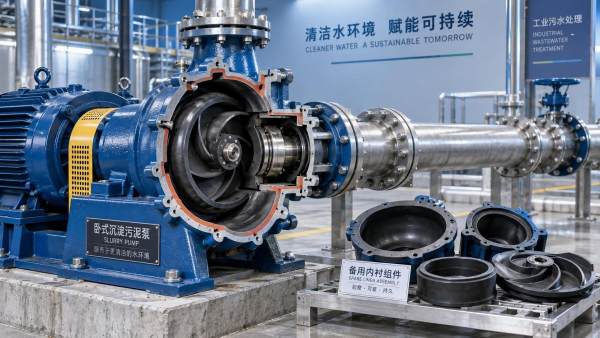
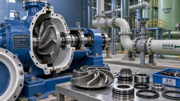
Wet-end components include the impeller, throatbush, volute or casing liner, frame plate liner, and other parts exposed directly to slurry. For highly abrasive, neutral-pH mineral slurries, high-chrome white iron is widely used because it offers good resistance to sliding abrasion. It is often appropriate for hard, fine-to-medium particle applications where impact is not excessive.
Elastomer linings can perform well with fine particles and conditions where resilience helps absorb particle impact. They may be less suitable for sharp coarse solids, high temperatures, oils, solvents, or chemical conditions that attack the elastomer. Polyurethane and other specialty materials can also be suitable in particular duties, but they should be selected against verified operating conditions rather than by a generic claim of “better wear resistance.”
Material selection should consider where wear occurs. A pump may show rapid damage at the impeller eye because of high inlet velocity, at the throatbush because of localized turbulence, or at the volute because particles strike a particular zone. Replacing all parts with a harder material does not always resolve the underlying hydraulic cause.
Check suction conditions and avoid cavitation
Cavitation occurs when pressure at the pump inlet falls low enough for vapor bubbles to form and collapse. In a slurry pump, cavitation can cause noise, vibration, declining performance, and accelerated damage. Abrasive solids make the damage worse because the pump is already operating in a harsh wear environment.
Compare the system’s available net positive suction head (NPSH available) with the pump’s required NPSH at the intended slurry duty. This assessment should include suction lift or static head, liquid level, pipe losses, suction pipe diameter, temperature, and fittings. A short, generously sized suction line with minimal restrictions is usually preferable to a long suction line with multiple bends.
Do not attempt to correct poor suction conditions by simply increasing pump speed. Higher speed can increase NPSH required, worsen inlet conditions, and shorten component life. Better options may include lowering the pump relative to the source vessel, increasing suction pipe diameter, reducing suction losses, changing the pump configuration, or using a booster arrangement where appropriate.
Evaluate speed, power, and control method together
Slurry pumps are frequently adjusted by changing impeller diameter, rotational speed, pulley ratio, or variable-frequency drive settings. These options affect more than flow. As speed increases, head rises sharply and power demand rises even faster. A drive sized for a water test point may not have sufficient margin once slurry density and process variations are included.
Confirm that the motor, gearbox or belt drive, coupling, bearings, and baseplate are rated for the full expected operating envelope. The selected motor should accommodate the maximum credible slurry density and operating speed without routinely approaching overload. A variable-frequency drive can provide useful control where flow demand changes, but it does not remove the need for a correct hydraulic selection. The pump still needs to operate in a stable range at the expected speeds.
Where a fixed-speed pump is used, impeller trimming may help place the normal duty closer to BEP. However, trimming reduces future head capability. It should be considered against expected liner wear, pipeline changes, and any planned increase in throughput.
Do not treat sealing as an afterthought
The shaft seal must suit the suction pressure, discharge pressure, solids content, water availability, and tolerance for leakage. Common arrangements include packed glands, expeller seals, and mechanical seals. Each has practical limits.
A packed gland can be robust and serviceable in many slurry duties, but it typically needs clean gland water at the correct pressure and flow to protect the packing and sleeve. Poor-quality seal water, inadequate pressure, or interrupted supply can lead to rapid sleeve damage and slurry leakage. An expeller seal can reduce or eliminate seal-water demand in some services, but its performance depends on operating conditions and it may not be suitable where the pump must run at low speed or standstill under pressure. Mechanical seals can be appropriate for controlled leakage requirements or certain process constraints, yet abrasive slurry places demanding requirements on seal design, flush plans, and operating discipline.
Choose the seal based on the real plant utilities and maintenance practice. A technically suitable seal that depends on reliable flush water is not a good choice where that water cannot be maintained.
Plan for wear life, not just initial performance
Abrasive ore pumps change as components wear. Clearance increases, efficiency decreases, head falls, and power behavior may shift. The useful question is not only whether the pump meets duty when new, but whether it can maintain acceptable operation until the next practical shutdown.
Ask how wear will be monitored. Pressure gauges, flow measurements, motor load trends, vibration monitoring, and regular inspection of wet-end clearances can reveal deterioration before production becomes unstable. Keep records by pump position and ore type when possible. A transfer pump may experience different wear patterns after changes in grinding, classification, dilution water, or pipeline routing.
Maintenance access also affects the right selection. Consider lifting space, liner replacement procedure, spare-part availability, rotating assembly removal, and whether the installation allows safe inspection. A slightly more expensive configuration may be preferable if it reduces the time and complexity of planned wet-end maintenance.
Frequently asked questions
Can I use a centrifugal water pump for abrasive ore slurry?
Usually not for sustained service. A conventional water pump may produce the required flow initially, but its thin wet-end components, narrow passages, sealing arrangement, and bearing design are generally not intended for abrasive solids. For ore handling, use a slurry pump designed for solids passage and replaceable wear components.
Should I select the hardest available wet-end material?
Not automatically. Hardness is valuable against sliding abrasion, but coarse impact, corrosion, temperature, and chemical exposure can change the preferred material. The best material is the one matched to the dominant wear mechanism in the specific slurry.
How much spare capacity should a slurry pump have?
Allow capacity for predictable changes such as liner wear, normal solids variation, and realistic pipeline resistance. Avoid excessive margin that forces routine operation far from BEP or creates over-velocity in the pipe. The useful margin should be based on the system curve and expected operating range.
Why does pump capacity drop after a period of operation?
Wear can enlarge impeller and liner clearances, reducing the pump’s ability to generate head. Other causes include a blocked suction, air ingress, a change in slurry density, pipeline buildup, a reduced pump speed, or cavitation. Inspect both the pump condition and the system before assuming the impeller alone is responsible.
What information should be sent for a slurry pump selection?
Provide required flow, total dynamic head, pipe size and length, elevation profile, suction arrangement, solids specific gravity, solids concentration, particle-size distribution, maximum particle size, temperature, pH or chemical conditions, operating schedule, and expected process variations. This information allows the pump curve, material choice, seal arrangement, and motor rating to be evaluated as one duty rather than as separate assumptions.
Related Information
 Oct 04, 2026
When custom slurry pumps make sense for nonstandard process duty
Custom Slurry Pumps reduce wear, blockage, downtime, and lifecycle costs in demanding nonstandard process duties. Learn when tailored pump engineering delivers measurable value.- Oct 03, 2026
Selecting pumps for flue gas desulfurization systems with gypsum slurry
Flue Gas Desulfurization Systems pump selection guide: optimize gypsum slurry handling with wear-resistant materials, reliable sealing, and lower lifecycle costs. - Oct 02, 2026
How abrasive slurry handling reduces premature impeller wear
Abrasive Slurry Handling reduces premature impeller wear through optimized velocity, material selection, suction control, and inspection strategies. Discover practical maintenance tips. - Oct 01, 2026
How mining slurry pumps affect downtime in high-wear circuits
Mining Slurry Pumps can make or break uptime in high-wear circuits. Learn how smarter selection, wear materials, and maintenance reduce failures and lifecycle costs.


Get a Quote
Please leave your information and email address, and we will contact you as soon as possible.