
Can you get remote support for slurry pump installation overseas?
Yes. Remote technical support for slurry pump installation abroad is practical when the installation is prepared as an engineering activity rather than a simple video call. A qualified support team can review drawings and photographs before equipment is set, guide alignment and piping checks during installation, observe commissioning through live video, and help isolate faults during initial operation. The quality of the outcome depends on the information available from site, the connection quality, and whether the local installation crew can carry out physical measurements accurately.
Remote support is most effective for pump placement, foundation verification, coupling alignment, suction and discharge piping review, seal-water connections, lubrication confirmation, rotation checks, and controlled start-up. It is less suitable when the pump has suffered transport damage, the baseplate requires machining or grouting correction, lifting arrangements are unsafe, or an internal inspection is needed after a serious mechanical event. Those situations may require a competent person on site, but remote diagnosis can still clarify what must be inspected before a visit is arranged.
Start with the installation package, not the live call
A slurry pump is sensitive to installation details that may appear minor on a general water-pump system. Slurries impose higher hydraulic loads, accelerate wear, and can expose piping weaknesses quickly. Before remote commissioning begins, the support engineer needs a coherent installation package. A few disconnected photographs of the pump rarely show whether the system is ready.
The package should identify the pump model, wetted material configuration, impeller diameter if applicable, drive arrangement, intended slurry density, estimated particle size, duty flow, total head, motor data, and the actual piping layout. Include the pump general arrangement drawing, foundation drawing, process line diagram, motor nameplate image, coupling type, and any seal or flush-water arrangement. Site photographs should show the complete pump train from several angles, not only close-ups of individual bolts or gauges.
It is also useful to label photographs with location and direction of view. A photo taken from the suction side, discharge side, drive end, and non-drive end prevents confusion when instructions are given across time zones. For large horizontal slurry pumps, a short slow video around the baseplate often reveals pipe strain, missing supports, awkward access around the bearing assembly, or an unprotected coupling guard location that a still image does not show.
Foundation level, baseplate support, and alignment are separate issues
Remote assistance often begins with “the base is level,” but that statement does not establish that the pump and drive are aligned. These are related conditions with different failure modes. A baseplate can be level while the motor and pump shafts are offset. A correctly aligned coupling can move out of tolerance after grout cures, pipework is connected, or the operating temperature changes.
The support session should establish whether the baseplate is continuously supported, whether grout has filled the intended areas, and whether hold-down bolts are tightened in the correct condition. Shims should be clean, flat, and fully supported rather than stacked loosely at one edge of a foot. Soft foot must be checked before final alignment: if tightening one motor foot changes the shaft position, the alignment reading is not reliable until that foot condition is corrected.
Alignment instruments are not interchangeable in the way their readings are interpreted. Dial indicators, laser systems, and straightedge methods can all reveal an obvious problem, but a remote engineer needs to know the instrument used and the actual readings, not only that alignment was “passed.” The coupling manufacturer’s requirements and the pump train geometry determine the acceptable values. Cold alignment must also account for expected thermal movement when the driver, bearing housing, or process temperature changes during operation.
For a belt-driven unit, pulley alignment, belt tension, and shaft center distance require separate attention. A pump that appears aligned at the coupling may still experience bearing load from incorrectly positioned sheaves. For direct-driven pumps, do not rotate the motor or pump independently without confirming that the coupling arrangement permits it and that no lockout condition is being defeated.
Pipe strain is one of the most frequent remote commissioning findings
Slurry pipelines are often heavy, lined, and supported over long distances. If the final pipe spool pulls the suction or discharge flange into position, the pump casing becomes part of the pipe support system. That can distort the casing, move the shaft centerline, overload bearings, and make an otherwise correct alignment reading meaningless after the bolts are tightened.
A useful remote verification method is to document the flange gap and parallelism before final connection, then observe any movement at the pump feet or coupling as flange bolts are tightened. The pipe should meet the pump flange naturally within the installation tolerance specified for the equipment. Jacking the line into position, using flange bolts to draw it across a visible gap, or forcing a twist into a rubber-lined spool should be treated as a corrective-work issue rather than an acceptable fit-up method.
The suction arrangement deserves close review because many start-up complaints originate there. A pump can fail to prime, lose capacity, surge, or produce cavitation-like noise for reasons that are not inside the pump. An air leak at a suction flange, insufficient submergence, a vortex at the sump, a blocked suction strainer, or a line that retains air at a high point can create similar symptoms. Video of the sump level and suction line is often as valuable as vibration readings from the pump.
Where an inlet isolation valve is installed, its bore and opening position matter. A partially opened valve, a damaged liner, or a gate that does not retract fully changes inlet resistance. On a suction line handling abrasive slurry, inspection must also consider liner condition and accumulated solids rather than assuming a valve is open because its handwheel position appears correct.
What a live remote start-up session should cover
A remote session works best when it follows the sequence of energy flow and slurry flow through the equipment. The person at site should have a stable phone or tablet connection, a second device if possible, adequate lighting, and safe access to gauges and the control panel. A hands-free camera is preferable to holding a device near rotating equipment.
- Before energizing the drive, verify that guards are fitted where required, lubrication points have received the specified lubricant, coupling fasteners are secure, and the pump can be turned only if the design and isolation state allow it.
- Confirm the direction of rotation with the coupling separated or another approved method when reverse rotation could damage the pump or prevent correct priming. Do not use a prolonged dry run to establish direction.
- Establish the liquid condition at suction. The support engineer needs to know whether the casing is flooded, whether the pump relies on a priming arrangement, and whether the slurry line contains settled material.
- Record baseline readings during the first controlled run: suction condition, discharge pressure, motor current, bearing temperature trend, vibration observation, gland leakage where relevant, and any unusual sound.
- Increase operating load only after the initial readings are stable. A discharge valve position that is appropriate for a clean-water check may be unsuitable for the intended slurry duty.
Measurements should be logged with the operating condition beside them. A discharge pressure has limited diagnostic value without flow, slurry concentration, impeller size, speed, and suction condition. Similarly, motor current cannot be judged against the nameplate alone. High current can indicate excessive flow, excessive slurry density, mechanical contact, an incorrect impeller, or a system condition that differs from the design basis. Low current can accompany low flow, air entrainment, lost prime, or a partially blocked suction.
Distinguish process symptoms from mechanical symptoms
Remote troubleshooting becomes much faster when observations are separated by when they occur. A pump that vibrates immediately after start-up with water in the casing may have an alignment, foundation, rotating assembly, or pipe-strain issue. Vibration that appears only after solids are introduced points more strongly toward slurry concentration, uneven feed, suction instability, particle accumulation, or a duty point outside the intended range.
A rising bearing temperature also needs context. Temperature that climbs steadily from the first minutes of operation can result from lubrication error, preload, contamination, shaft misalignment, or bearing damage. A temperature increase after the pipework reaches process temperature may indicate thermal movement or load transmitted through piping. A single surface temperature image is useful, but the trend and the location of the reading are more informative than an isolated number.
Seal-area leakage should not be diagnosed from appearance alone. Packed glands require an appropriate controlled leakage condition to cool and lubricate packing; a completely dry gland can overheat and damage the sleeve. Mechanical seal systems need confirmation of the correct flush, barrier, or quench arrangement where fitted. Leakage that contains abrasive solids, sudden leakage after a pressure change, or leakage accompanied by heat at the seal chamber warrants immediate examination of operating conditions rather than repeated tightening.
Communication controls that prevent rework
Time-zone differences and multilingual site teams can turn a straightforward correction into several days of delay. Remote support should have one agreed technical contact at site, a defined call time, and a record of instructions, readings, and open actions. Use marked-up drawings or annotated photographs for changes such as shim adjustments, support locations, valve positions, and instrument connection points. Verbal descriptions such as “the left flange” are unreliable when participants face opposite sides of the pump.
Do not combine fault finding with unrecorded design changes. If a support engineer recommends reducing speed, changing an impeller, adjusting a gland, or modifying pipe supports, record the original condition and the reason for the change. This preserves a clear commissioning history and avoids treating a temporary diagnostic adjustment as a permanent operating setting.
Remote assistance should also establish stop conditions before the pump is started. Persistent metallic contact, rapidly increasing bearing temperature, loss of prime, visible casing or pipe movement, abnormal motor loading, failure of a seal support system, or unsafe access around rotating equipment are reasons to stop and investigate. Continuing a test merely to obtain more data can convert a correctable installation issue into damage to the wet end, shaft, bearings, or liner system.
Prepare for remote support before equipment reaches site
Overseas installations benefit from planning at the packing and transport stage. Keep manuals, assembly drawings, wiring diagrams, recommended spare parts, and inspection records available digitally as well as with the shipment. Confirm that lifting points, baseplate dimensions, flange standards, power supply characteristics, and instrumentation interfaces match the site arrangement before the pump is positioned. A mismatch discovered after grouting or piping is complete is far harder to correct through a camera.
For abrasive duties, verify the actual material selection against the slurry description. High-chrome wear components, elastomer-lined parts, polyurethane elements, and corrosion-resistant alloys respond differently to particle shape, particle size, solids concentration, pH, and temperature. Remote support can identify an apparent mismatch between duty and installed configuration, but it cannot substitute for accurate process information supplied before commissioning.
The pump should be considered together with the isolation and control components around it. A valve intended for abrasive slurry service must have a suitable flow path, liner or wear-resistant surfaces where needed, and an installation orientation that permits full operation and maintenance access. Near the end of the commissioning process, reviewing connected slurry-line hardware such as a Leak-free Heavy-duty Wear-resistant Knife Gate Valve(Heavy-duty Type) can help confirm that the pump is not being tested against an unintended restriction or an incorrectly configured isolation point.
Related Information
 Oct 24, 2026
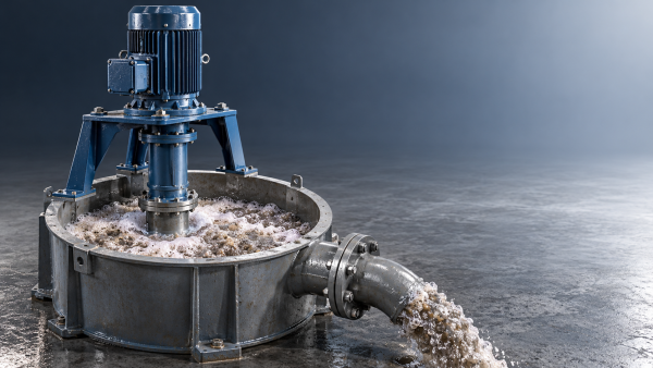
How Much Should a Froth Pump Be Oversized for Flotation Concentrate?
How much should a froth pump be oversized for flotation concentrate? Learn how inlet air, peak flow, and head affect sizing to avoid costly mistakes and select the right pump.- Oct 24, 2026
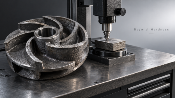
Is Higher Hardness Always Better for High-Chrome Pump Castings?
Is higher hardness always better for high chrome pump castings? Discover how toughness, carbide structure, and slurry conditions affect service life—and choose smarter to reduce downtime. - Oct 23, 2026
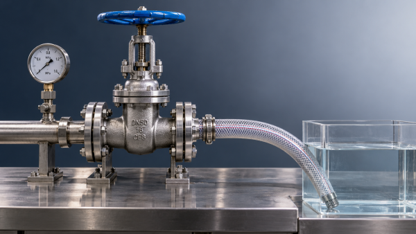
Which Leakage Test Should You Specify for a Zero-Leakage Knife Gate Valve?
Which leakage test should I specify when ordering a zero-leakage knife gate valve? Compare API 598 and ISO 5208, define seat leakage limits, and avoid costly purchasing mistakes. - Oct 23, 2026
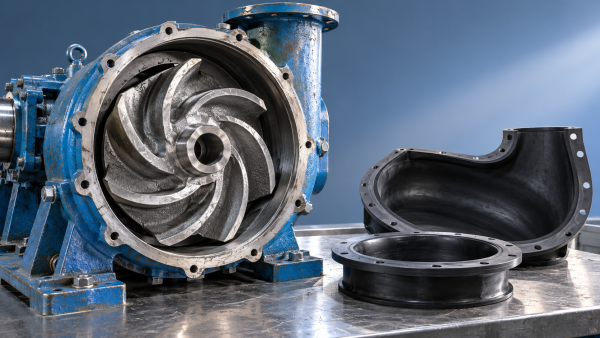
Which Pump Material Lasts Longest in Limestone-Gypsum FGD Slurry?
Which pump material lasts longer in limestone-gypsum desulfurization slurry? Compare high-chrome iron, rubber and duplex steel to find the right fit, reduce downtime and extend service life.

{item.title}
Get a Quote
Please leave your information and email address, and we will contact you as soon as possible.