
Are CFD-Optimized Pumps Better at Preventing Clogging?
Often, yes, but only when the CFD work has been used to solve the actual solids-handling problem. A pump described as “CFD-optimized” is not automatically more resistant to clogging than a conventional design. The benefit depends on what was modeled, which operating point was prioritized, the size and behavior of the solids, and whether the installed system keeps the pump near its intended duty point.
For wastewater, sludge, slurry, fibrous waste, and process streams containing irregular debris, anti-clogging performance is governed by flow paths more than by headline efficiency. Computational fluid dynamics can expose recirculation pockets, abrupt directional changes, low-velocity zones, and blade-leading-edge impacts that may trap or accumulate solids. When designers use those findings to reshape the wet end, CFD can produce a pump that clears solids more consistently. When it is used mainly to improve the best-efficiency-point curve, the anti-clogging claim may be far less meaningful.
What CFD Can Improve in an Anti-Clogging Pump
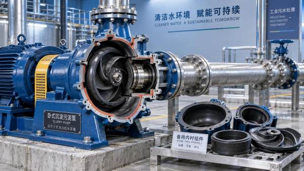
CFD allows designers to examine how liquid moves through an impeller, volute, suction passage, wear-clearance area, and discharge channel before casting parts or building prototypes. In a clean-water pump, the analysis may focus heavily on head, efficiency, and pressure distribution. In a solids-handling pump, the more useful question is whether the internal hydraulic passage remains open and energetic enough for the expected solids to pass through it.
A well-executed CFD study can help identify several conditions associated with blockage risk:
- Low-velocity regions where fibrous material, sediment, or sticky solids can settle.
- Recirculation zones behind blades, near the cutwater, or around shroud and hub transitions.
- Sharp pressure changes that encourage solids to separate from the main flow stream.
- Flow incidence at the impeller inlet that can pull rags or stringy material toward blade edges.
- Internal passage shapes that accept a nominal solid size but create a restriction at another point in the hydraulic path.
- Uneven loading that causes vibration, unstable operation, or rapid wear, all of which can worsen passage performance over time.
This is especially relevant for non-clog, vortex, channel, and recessed-impeller designs. These pump types use different strategies to move solids, and each has distinct areas where flow behavior matters. A wide passage alone does not guarantee reliable operation. If the flow slows dramatically in that passage or drives material into a stagnant pocket, the opening may still foul.
CFD Is More Useful When It Includes Solids Behavior
A common source of confusion is that fluid-flow optimization and anti-clogging optimization are related but not identical. Standard CFD can show liquid velocity, pressure, turbulence, and cavitation tendencies. Those results are valuable, yet water-like flow fields do not fully represent how wipes, hair, string, plastic film, mineral particles, agglomerated sludge, or abrasive slurry behave in service.
For an anti-clogging claim to carry weight, the design process should go beyond a clean-liquid simulation. Depending on the application, that can include particle tracking, multiphase modeling, non-Newtonian fluid assumptions, or analysis of elongated and flexible contaminants. None of these methods perfectly predicts every blockage event, particularly with rags and mixed debris. They do, however, make it easier to compare internal geometries and identify designs likely to create retention points.
The practical question for a buyer is not simply whether CFD was used. It is whether the manufacturer modeled conditions similar to the pumped medium. A pump intended for screened municipal wastewater faces a different solids profile from a pump handling raw influent, digested sludge, food-processing byproducts, paper stock, or mineral slurry. A simulation based on uniform hard particles may provide limited evidence for a stream dominated by flexible fibrous material.
Passage Geometry Still Sets the Physical Limit
No amount of flow simulation can make an undersized solids passage reliably pass objects larger than its smallest effective opening. Pump literature may state a maximum sphere passage, but that number should not be interpreted as a guarantee for every object of that size. A round solid behaves very differently from a rag bundle, wire, strip of plastic, or long fiber.
Buyers should identify the actual contaminant profile before selecting a hydraulic design. The following details are more useful than a generic statement that the liquid “contains solids”:
- Largest expected hard solids and their shape.
- Presence and approximate frequency of wipes, textiles, hair, string, film, or other fibrous debris.
- Solids concentration and whether material settles quickly when velocity falls.
- Particle abrasiveness and the expected rate of wear.
- Fluid viscosity, temperature, gas content, and tendency to form deposits.
- Whether the installation sees intermittent flow, long idle periods, or reverse flow events.
CFD can refine a suitable geometry after these conditions are known. It cannot compensate for unclear process information or a pump selected around an unrealistic solids description.
Where CFD-Optimized Designs Can Deliver a Real Advantage
The strongest case is usually found where the pump must handle troublesome solids repeatedly and where a blockage creates a costly interruption. Lift stations, headworks-adjacent duties, industrial wastewater systems, sludge transfer, food-waste handling, pulp and paper processes, and certain chemical-process slurries can all justify closer attention to internal flow design.
In these duties, a CFD-led redesign may improve reliability through smoother inlet guidance, fewer dead zones, more continuous velocity through the impeller, and a cleaner discharge path. It may also reduce the chance that debris wraps around a blade or accumulates at a clearance transition. Those improvements can matter more than a small gain in nominal hydraulic efficiency because each manual cleanout, emergency callout, or unplanned shutdown carries operational consequences beyond electricity use.
The advantage is less certain in a duty where solids are minimal, predictable, and well screened. A conventional pump with a proven open passage and a sound installation may perform equally well. Similarly, a design that performs well at its rated point can lose its anti-clogging behavior when it is operated far below flow, repeatedly cycles on and off, or sees conditions outside its original design envelope.
Why a Better Pump Can Still Clog
Anti-clogging performance is a system outcome, not only an impeller feature. A CFD-optimized pump can still suffer fouling when the suction arrangement promotes vortices, the wet well allows solids to settle, the line velocity is inadequate, or the pump is operated at a severely throttled condition. Pipework geometry, control settings, check-valve behavior, and maintenance practices all influence whether debris reaches and passes through the pump in a stable manner.
Operating too far left of the preferred operating region is a recurring problem. At low flow, internal recirculation tends to increase and solids may spend more time in areas where they can collect. The pump may continue to develop pressure, giving the impression that it is functioning, while deposits or fibrous material are gradually building inside the hydraulic passage.
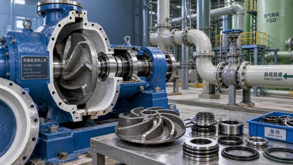
Wear changes the picture as well. In abrasive slurry service, enlarged clearances and eroded contours can alter the flow pattern that the original CFD model predicted. In wastewater service, deposits can roughen surfaces and narrow passages. A design should therefore be judged not only by its new-pump performance but by how its wear components, clearances, inspection access, and rebuild procedure support reliable operation across its service interval.
Questions That Separate a Design Claim From a Useful Selection Basis
When evaluating whether a CFD-optimized pump is really better for anti-clogging, ask for engineering information tied to the duty rather than a general statement about simulation capability. A supplier should be able to discuss the hydraulic concept in practical terms: where solids travel, where material might accumulate, and why the chosen geometry addresses those locations.
It is also reasonable to compare the claimed design against the maintenance burden of the existing installation. Repeated blockages may indicate a pump problem, but they may also point to changes in incoming waste, failed screening, poor wet-well cleaning, incorrect pump rotation, unsuitable controls, or a duty point that has shifted as the system changed.
Do Not Treat Efficiency and Clog Resistance as Opposing Goals
There is a tendency to assume that a pump must sacrifice efficiency to pass solids. Some compromises are unavoidable: a large open passage, recessed impeller, or vortex arrangement may not achieve the same efficiency profile as a tightly engineered clean-water pump. Yet CFD gives designers more opportunity to manage that compromise deliberately.
By reducing unnecessary separation and recirculation while preserving a clear solids path, a design may improve both hydraulic performance and resistance to accumulation. The result will depend on the pump type and duty. A buyer should be cautious of claims that promise maximum free passage, maximum efficiency, zero ragging, and identical performance across every operating condition. Those objectives conflict in many real applications.
A more credible selection process defines priorities. Where downtime and manual intervention are the dominant costs, a hydraulically forgiving pump with easier service access may be preferable to a design that offers a stronger efficiency figure at one narrow operating point. Where energy use is substantial and solids are controlled, a more efficient channel design may be appropriate, provided its passage and operating range match the process.
The Decision Is About Evidence, Not the CFD Label
CFD is a valuable design tool for reducing clogging risk because it reveals flow conditions that are difficult to see from drawings or traditional performance curves alone. It is most persuasive when it has informed a solids-specific hydraulic design, when the physical passage suits the actual contaminants, and when the pump will operate within the range considered during design.
For a difficult solids-handling duty, a CFD-optimized pump deserves closer consideration than a pump selected only by flow, head, and nominal solids passage. But the label should be treated as a starting point for technical questions, not as proof of reliable anti-clogging performance. The final selection should connect the pump geometry, modeled conditions, expected debris, operating point, and installation layout into one defensible decision.
Related Information
 Oct 04, 2026
When custom slurry pumps make sense for nonstandard process duty
Custom Slurry Pumps reduce wear, blockage, downtime, and lifecycle costs in demanding nonstandard process duties. Learn when tailored pump engineering delivers measurable value.- Oct 03, 2026
Selecting pumps for flue gas desulfurization systems with gypsum slurry
Flue Gas Desulfurization Systems pump selection guide: optimize gypsum slurry handling with wear-resistant materials, reliable sealing, and lower lifecycle costs. - Oct 02, 2026
How abrasive slurry handling reduces premature impeller wear
Abrasive Slurry Handling reduces premature impeller wear through optimized velocity, material selection, suction control, and inspection strategies. Discover practical maintenance tips. - Oct 01, 2026
How mining slurry pumps affect downtime in high-wear circuits
Mining Slurry Pumps can make or break uptime in high-wear circuits. Learn how smarter selection, wear materials, and maintenance reduce failures and lifecycle costs.


Get a Quote
Please leave your information and email address, and we will contact you as soon as possible.