
What Causes Rapid Impeller Wear in Slurry Pumps?
Rapid impeller wear in a slurry pump is usually caused by a mismatch between the slurry, the pump's operating point, and the impeller material or geometry. Abrasive solids are expected in slurry service, but wear accelerates sharply when particles are coarse or angular, solids concentration rises, velocity is excessive, the pump runs away from its best efficiency point, or the impeller is made from a material unsuited to the duty.
The immediate result is more than a shorter parts-replacement interval. As impeller passages open up and hydraulic surfaces lose their intended shape, pump efficiency drops, power demand can become less predictable, pressure capability falls, and recirculation often increases. A pump may still move liquid, yet fail to deliver the required head or capacity. That is why rapid wear should be treated as a system condition to investigate, rather than simply a consumable-parts issue.
Abrasion depends on more than solids content
It is tempting to assume that a slurry with more solids will always wear an impeller faster. Concentration matters, but it is only one part of the wear mechanism. Particle size, shape, hardness, density, and movement through the pump all influence how aggressively solids attack the wetted surfaces.
Large, sharp, hard particles tend to produce cutting and gouging wear. They strike the leading edges of impeller vanes, the shrouds, and the outer vane tips with enough energy to remove material. Fine particles can be damaging as well, particularly at high concentration. A dense fine slurry may act like an abrasive polishing compound, steadily thinning surfaces across a broader area. The resulting wear pattern may look smoother than damage from coarse particles, but service life can still be poor.
Particle shape is often underestimated. Rounded particles may slide through an impeller passage with relatively limited cutting action, while angular crushed material can repeatedly impact and scrape the same hydraulic surfaces. Two slurries with similar nominal particle size can therefore produce very different wear rates.
Hardness must also be considered in relation to the impeller alloy or elastomer. An impeller material that performs well with fine mineral tailings may be unsuitable for coarse, high-hardness aggregate or sharply angular ore. No material is universally best. A harder alloy may resist cutting abrasion better, while an elastomer lining can perform well where particles are finer and impact energy is lower. Once particle size and impact severity exceed the material's practical range, the apparent advantage disappears quickly.
Excessive velocity turns normal abrasion into rapid loss
Slurry pump wear is closely tied to particle velocity. Higher rotational speed increases the relative speed between the solids and the impeller surfaces. In many duties, this produces a disproportionate rise in wear because impact energy increases rapidly as velocity rises.
Running a smaller pump at high speed to meet a duty can therefore be costly, even when its flow and head appear acceptable on paper. The pump may meet the process requirement, but its impeller can see substantially higher abrasion than a properly sized, lower-speed alternative. This is especially relevant in applications where throughput has gradually increased and the existing pump is being pushed harder than its original design condition.
High speed is not the only way velocity becomes excessive. Narrow impeller passages, incorrect impeller diameter, excessive discharge throttling, and poorly selected pipework can all change flow patterns and local velocities. A partially closed discharge valve may control flow, but it also shifts the operating point and can create internal recirculation zones. Those zones expose surfaces to repeated particle movement rather than one clean pass through the pump.
Wear concentrated at the vane leading edge, eye region, or shroud entrance often points to high inlet velocity, poor inlet conditions, or recirculation near the impeller eye. Wear strongest at the vane tips and outer diameter may indicate high peripheral speed or heavy impact as particles are accelerated outward. The location of material loss is useful diagnostic evidence; it should be recorded before the impeller is discarded.
Operating too far from the best efficiency point creates internal wear zones
A slurry pump does not need to fail mechanically to be operating badly. When it runs far to the left or right of its best efficiency point, internal flow becomes less stable. Recirculation, turbulence, and uneven loading increase, causing solids to strike or circulate near surfaces that would see less exposure at the intended operating condition.
Low-flow operation is a common source of avoidable damage. If a pump is oversized and flow is repeatedly throttled back, liquid and solids can recirculate inside the casing and around the impeller. Instead of moving efficiently through the pump, particles remain in high-energy areas longer. This can lead to localized erosion, vibration, heat generation, and loss of hydraulic performance.
High-flow operation has different consequences. The pump may operate with insufficient head margin, higher inlet velocities, and altered incidence angles at the impeller inlet. Solids can strike vane leading edges more aggressively, while casing and throatbush wear may also increase. Where the duty has changed, operators should compare the actual flow, head, speed, density, and solids condition against the pump curve and the slurry performance correction used during selection.
Pressure gauges alone do not provide the full picture. A pump can show a seemingly acceptable discharge pressure while delivering less useful flow because impeller and clearance wear have already reduced hydraulic capability. Flow measurement, power trend data, vibration history, and inspection records give a more reliable basis for deciding whether the pump is operating in a stable range.
Watch for a changing duty, not just a worn part
Process changes frequently explain why an impeller that once lasted well begins wearing rapidly. Feed size may become coarser after upstream equipment changes. Slurry density can increase after a thickening or water-balance adjustment. A new ore body, recycled material stream, or different grinding condition may alter particle hardness and shape. Even seasonal water availability can affect concentration and viscosity.
These changes may be gradual enough that they are not immediately connected with pump wear. Comparing current slurry properties with the conditions assumed when the pump was selected is often more productive than repeatedly changing impeller materials without understanding the duty.
Material selection has limits
Choosing a more wear-resistant impeller material can extend life, but material selection cannot correct every operational problem. A high-chrome alloy impeller may tolerate severe sliding abrasion well, yet can be vulnerable to impact damage in some coarse-particle duties. Elastomer impellers can offer good resistance where fine particles and corrosion are important, but they may not withstand large sharp solids or high temperatures. Austenitic materials, duplex alloys, and other corrosion-resistant choices may be justified when chemical attack contributes to wear, but they are not automatically the best answer for severe abrasion.
The first question should be what type of damage is occurring. Abrasion and corrosion can act together. In an acidic or chemically aggressive slurry, corrosion may weaken the surface and make it easier for solids to remove material. An impeller that appears to be suffering from simple erosion may actually require a material with better corrosion resistance, a change in pH control, or a review of chemical additions.
Material decisions should be based on the particle characteristics, chemical environment, temperature, required service life, and failure pattern. Selecting solely by nominal hardness can be misleading. Hardness helps with certain abrasion mechanisms, but toughness, corrosion resistance, resilience, and the ability to tolerate impact may be equally important.
Clearances and adjacent components can accelerate impeller damage
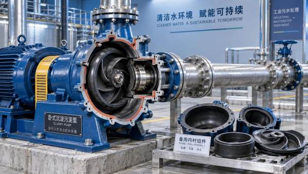
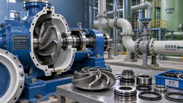
An impeller works with surrounding wear components, including the throatbush, liners, side liners, expeller, and shaft sealing arrangement. As these parts wear, clearances increase. More slurry can leak from the high-pressure region back toward the low-pressure region, reducing efficiency and disturbing flow around the impeller. The pump may then be driven harder or operated longer to maintain production, compounding wear across the wet end.
In adjustable-clearance designs, restoring the correct clearance can recover hydraulic performance and slow the deterioration that follows excessive internal leakage. However, adjustment should follow the manufacturer's limits and the condition of the complete wet end. Closing a clearance against badly distorted or worn parts can create rubbing, heat, or uneven contact without solving the underlying hydraulic problem.
Seal-water problems can also affect wear indirectly. Inadequate flushing or incorrect gland settings may allow solids to reach areas intended to remain protected. Although this does not always cause primary impeller erosion, it can increase shaft, sleeve, seal, and bearing problems that lead to unstable pump operation.
Cavitation and air entrainment are often misdiagnosed as abrasion
Cavitation damage can resemble erosive wear, especially when pitting appears near the impeller eye or on low-pressure surfaces. It occurs when local pressure falls low enough for vapor bubbles to form and then collapse as pressure recovers. The repeated collapse damages the material surface and can create vibration and noise. In a slurry pump, abrasive solids may then remove the already-weakened material more quickly.
Common causes include insufficient net positive suction head available, excessive suction lift, restricted suction piping, blocked strainers where they are used, low sump level, high slurry temperature, or a pump operating at an unsuitable speed or flow. Air entrainment creates related problems. Air entering through a vortex, leaking suction connection, poorly arranged sump, or turbulent inlet can disrupt flow and promote instability at the impeller eye.
A worn impeller should not automatically be blamed on cavitation simply because its surface is pitted. Inspecting the suction arrangement, checking for air ingress, reviewing operating noise and vibration, and comparing the damage location with the expected flow path help separate cavitation from ordinary abrasive erosion.
A practical investigation sequence
When impellers are wearing out faster than expected, replacing the part with the same material and setting may restore operation temporarily but rarely answers the cause. A useful investigation starts by documenting the failed component before cleanup or disposal. Photograph the wear pattern, note the remaining thickness at consistent points, and record which side of the impeller is most affected.
- Confirm actual pump speed, flow, discharge pressure, power draw, and slurry density during normal operation.
- Compare the operating point with the pump curve, including any correction needed for the slurry rather than clear water.
- Review recent changes in particle size, feed source, solids concentration, temperature, pH, and chemical additions.
- Inspect the throatbush, liners, casing, shaft sleeve, and sealing components for wear patterns that support or contradict the initial diagnosis.
- Check suction piping, sump conditions, fluid level, vortex control, and possible air-entry points.
- Verify impeller material, metallurgy or elastomer specification, and geometry against the actual slurry duty.
This sequence helps distinguish a material problem from a duty problem. It also prevents a common mistake: selecting a more expensive impeller alloy when the main cause is an oversized pump running throttled at low flow, or reducing speed when the actual issue is a coarser and more angular feed.
When replacement is no longer enough
A single unexpected wear event may follow an unusual process upset. Repeated short life, especially with a consistent damage pattern, usually justifies a review of pump selection and system operation. A larger pump running more slowly, a different wet-end material, a revised impeller design, improved inlet conditions, or upstream classification to remove oversize particles may each be appropriate depending on the cause.
The most useful decision is rarely “which impeller lasts longest?” It is which combination of pump speed, hydraulic design, material, operating range, and slurry control produces acceptable wear life without compromising process performance. Once the wear pattern is connected to actual operating conditions, impeller replacement becomes planned maintenance rather than a recurring production risk.
Related Information
 Oct 04, 2026
When custom slurry pumps make sense for nonstandard process duty
Custom Slurry Pumps reduce wear, blockage, downtime, and lifecycle costs in demanding nonstandard process duties. Learn when tailored pump engineering delivers measurable value.- Oct 03, 2026
Selecting pumps for flue gas desulfurization systems with gypsum slurry
Flue Gas Desulfurization Systems pump selection guide: optimize gypsum slurry handling with wear-resistant materials, reliable sealing, and lower lifecycle costs. - Oct 02, 2026
How abrasive slurry handling reduces premature impeller wear
Abrasive Slurry Handling reduces premature impeller wear through optimized velocity, material selection, suction control, and inspection strategies. Discover practical maintenance tips. - Oct 01, 2026
How mining slurry pumps affect downtime in high-wear circuits
Mining Slurry Pumps can make or break uptime in high-wear circuits. Learn how smarter selection, wear materials, and maintenance reduce failures and lifecycle costs.

Get a Quote
Please leave your information and email address, and we will contact you as soon as possible.