
Abrasive Slurry Handling: Where Pipelines, Pumps, and Valves Fail First
Abrasive slurry systems usually announce failure before a line ruptures or a pump stops. The first signs are often localized: a pipe spool thins near an elbow, discharge pressure begins to wander, a valve becomes difficult to stroke, or a seal area shows wet residue after a normal run. Treating these as isolated defects can lead to repeated replacements at the same point. In abrasive slurry handling, the location and pattern of damage usually reveal the mechanism behind it.
Solid particle size, shape, hardness, concentration, and transport velocity interact with pipe geometry and equipment condition. A system moving coarse, angular material behaves differently from one carrying fine mineral solids, even when nominal flow rate is similar. Changes in feed material, dilution water, or pump speed can therefore move the wear problem from one component to another.
Start With the Wear Pattern, Not the Failed Part
Before removing a failed component, record its position, orientation, service time, flow direction, operating pressure, and recent process changes. A worn lower pipe wall, for example, suggests settling or a low-velocity zone. A groove on the outside radius of an elbow usually points to particle impact at a directional change. Uniform internal thinning can indicate sustained high velocity, while sharply localized attack often comes from turbulence, misalignment, or an internal obstruction.
Inspection should distinguish abrasion from erosion-corrosion. Abrasion is mechanical removal caused by particles sliding or rolling across a surface. Erosion is more closely associated with high-energy particle impact, commonly at bends, reducers, tees, pump casings, and valve restrictions. Corrosion can weaken the exposed material and accelerate either mechanism where the liquid chemistry is aggressive. The remaining surface texture is useful evidence: broad polished wear, deep directional grooves, pitting, and jagged cavities do not point to the same corrective action.
A pressure record is equally valuable. A gradual rise in differential pressure across a fixed pipe section may indicate buildup, reduced bore, or a valve that is no longer opening fully. A falling discharge pressure with reduced flow may be associated with pump wear, internal recirculation, air ingress, or loss of available suction head. Sudden pressure pulses need separate attention because they can loosen linings, damage joints, and shorten the life of otherwise suitable components.
Pipeline Failures Usually Begin at Geometry Changes
Straight pipe can wear predictably when velocity and solids distribution remain stable. The most frequent early pipeline failures occur where flow turns, splits, contracts, expands, enters a vessel, or passes through a joint with an internal step. These locations disturb the particle path and concentrate impact energy on a smaller area.
Elbows deserve particular scrutiny. Their service life depends on bend radius, wall construction, slurry characteristics, and velocity. A tight-radius elbow may be necessary where space is limited, but it exposes the outer wall to greater particle impact than a long-radius bend. Rotating a symmetrical elbow can sometimes move a worn zone away from the impact path, provided its design, lining, supports, and connection arrangement permit it. Rotation is not a remedy for a system running beyond the velocity suitable for its material and lining.
Reducers create another common blind spot. A concentric reducer installed in a horizontal slurry line may create an unfavorable solids distribution if its geometry allows material to settle or accelerate unevenly. Eccentric reducers are often selected to control air pockets or maintain a preferred pipe elevation, but orientation matters. The flat side must match the intended flow condition and piping layout. A reducer with a worn downstream edge may be showing particle acceleration; wear at an upstream lip can indicate a protruding gasket, poor alignment, or an abrupt bore transition.
At tees, dead legs, and instrument branches, solids can settle when local velocity falls. Material packed in an unused branch can harden, obstruct a later inspection, and alter the main flow pattern. Blind branches should be minimized in slurry service. Where a branch is unavoidable, its orientation, flush arrangement, and isolation method should be considered during installation rather than after plugging occurs.
Pipe supports also affect internal wear. Unsupported heavy slurry lines can sag, placing bending stress on flanges and couplings while changing alignment at adjacent components. Rigidly fixing every support point can be just as problematic if thermal movement, hose movement, or pump vibration has no controlled path. A support inspection should look for broken clamps, worn sliding surfaces, contact between pipe and structure, and signs that a flexible connection is being forced to absorb misalignment.
Velocity Has a Narrow Useful Range
Slurry transport requires enough velocity to prevent sustained settling, but excessive velocity increases wear rapidly at bends, valves, and pump wetted parts. The appropriate range cannot be set from pipe diameter alone. It depends on particle settling behavior, concentration, liquid viscosity, pipe route, and whether operation is continuous or intermittent. A line that remains clear during steady production may settle during low-speed startup, a process hold, or an extended shutdown.
Where settling is suspected, avoid simply increasing pump speed until the pressure looks normal. The restriction may be partial and unstable; forcing flow through it can create high local velocity and damage a weakened pipe section. Confirm the line condition through approved isolation, flushing, inspection ports, or planned disassembly. Restart procedures should establish adequate transport conditions promptly and avoid extended operation in the range where solids deposit.
Pumps Show Damage Through Hydraulic Instability
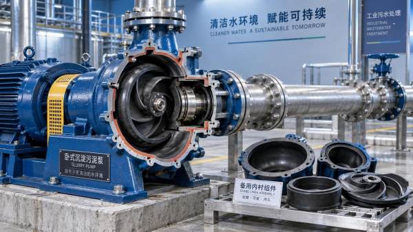
Slurry pumps tend to lose performance through a combination of impeller wear, liner wear, clearance growth, seal problems, and suction-side disturbances. The pump may continue to run while its efficiency declines, so discharge pressure and flow trend data are more useful than a single observation. A pump operating at the same speed but requiring a more open downstream valve to maintain flow may have internal wear or a changing slurry condition.
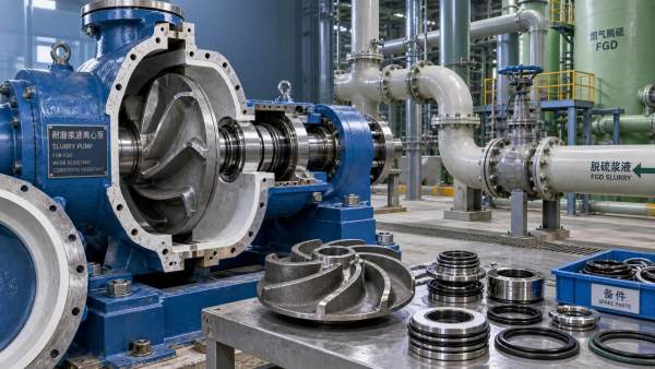
The impeller is exposed to both sliding abrasion and impact. Wear at vane leading edges can reduce pumping action; erosion around the eye can alter inlet flow and increase recirculation. Clearance between the impeller and throatbush or liner is also important. As clearance grows, internal leakage rises and the pump may need more speed to meet the same duty. Increasing speed can restore output temporarily, but it also raises wear loading and may transfer the problem to the pipeline.
Inspect casing liners and throat areas for localized loss of material. A liner worn near the inlet may be connected to poor suction conditions, while heavy discharge-side wear can reflect high velocity or a duty point outside the pump's intended operating region. Material selection should follow the slurry rather than habit. Hard metal liners can tolerate many high-abrasion duties, while elastomer linings may suit fine particles where impact conditions and chemical compatibility are acceptable. Neither material is universally correct; large sharp particles and high-impact zones can damage an elastomer, while corrosion or certain particle conditions may limit a metallic material.
Cavitation is commonly blamed whenever a pump is noisy, but noise alone is not proof. Air entrainment, loose mounting, bearing damage, suction blockage, and recirculation can create similar symptoms. Look for fluctuating suction and discharge readings, frothy return flow, unusual vibration trends, damage near the impeller eye, and changes after a tank level or feed condition shift. If cavitation is confirmed, examine the entire suction arrangement: liquid level, suction pipe diameter, bends close to the inlet, blocked strainers where used, air leaks, and the possibility that solids are accumulating before the pump.
Seal failures also need context. A leaking mechanical seal may result from dry running, shaft movement, excessive pressure, incompatible flush conditions, or solids entering the seal chamber. Replacing the seal without checking shaft sleeve wear, bearing condition, seal water availability, and flush line blockage can repeat the failure quickly. Packing arrangements require their own discipline: excessive tightening can generate heat and score the sleeve, while insufficient adjustment can allow unacceptable leakage and solids ingress.
Valves Fail Where They Throttle or Trap Solids
In abrasive slurry service, a valve intended only for isolation should not routinely be used for throttling. Partially open gates, knife gates, butterfly valves, and other designs can create a high-velocity jet that erodes seats, discs, sleeves, and downstream pipe. A valve may still appear closed or open from the outside while its internal sealing surfaces have lost the ability to isolate effectively.
Valve selection begins with the actual duty: isolation, control, diversion, drain, or emergency shutoff. The required direction of pressure, expected solids size, operating frequency, and need for full-bore passage all affect the suitable design. A full-port slurry valve reduces obstruction when fully open, but it does not eliminate wear if it is repeatedly throttled. Where control is necessary, a purpose-selected control valve or a layout that places the pressure drop in a replaceable wear component may be more maintainable than sacrificing an isolation valve.
Sticking during actuation can arise from solids packed around a gate, deposits in the seat area, actuator force that has drifted out of adjustment, or stem and linkage problems. Do not apply increasing force without understanding the obstruction. Forcing a partially jammed valve may bend a stem, damage an actuator, or drive abrasive material deeper into a sealing surface. Isolate and depressurize the section, then inspect for trapped solids, worn guides, damaged sleeves, and signs that the valve body is distorted by pipe loads.
Small bypasses, drain valves, sampling valves, and pressure taps often fail sooner than the main isolation valve because their bores are narrow. They may plug, erode through, or give misleading readings. Their location should allow flushing and safe access. A pressure gauge connected through a solids-filled impulse line does not describe the active process condition; it describes the condition inside the blocked connection.
In high-solids applications such as Dredging Industry, valve placement should also account for shutdown behavior. Material that remains motionless in a low point can compact before the next start. Drain and flush points must be positioned to clear the actual low areas of the route, rather than simply placed where installation is convenient.
Installation Details That Create Premature Wear
Many recurring failures originate in assembly. A gasket protruding into the bore becomes a particle strike point. A mismatched internal diameter at a flange creates a step that erodes downstream metal or lining. Misaligned pipe can place side load on a pump casing or valve body. Weld spatter, sharp internal weld profiles, and incomplete lining transitions can all initiate turbulence.
During planned work, inspect mating bores before tightening fasteners. Confirm that replacement spools have the specified wall thickness, lining, flange rating, and face-to-face dimension. A component that fits between flanges is not necessarily equivalent in slurry duty. For lined piping, verify that the liner is continuous at joints and that tightening sequence does not damage the lining or distort the flange face.
- Mark the original orientation of worn elbows and reducers before removal; the mark preserves evidence of the particle path.
- Measure remaining wall thickness at repeated locations rather than relying only on external appearance. Ultrasonic readings need an appropriate method where linings or rough internal surfaces are present.
- After a pump rebuild, confirm rotation, coupling alignment, guard installation, seal support connections, and unobstructed suction conditions before introducing solids.
- Record valve position against actual flow response. A position indicator can be inaccurate when internal components are worn or obstructed.
Use Failure Timing to Set Inspection Intervals
Inspection intervals should be based on observed wear rate, service variability, and the consequence of a leak or blockage. A newly commissioned system needs closer observation because installation defects and unexpected flow behavior tend to appear early. Once a stable wear pattern is understood, thickness measurements, pressure trends, vibration observations, and component history can be used to plan replacement before containment is threatened.
Do not assume identical parts will wear identically. One elbow may last longer because it sees a different solids distribution, receives flow after a pump, or sits near a branch connection. A replacement history should identify location and failure mode, not only part number and date. That record is most useful when linked to operating changes such as different feed grading, altered water addition, reduced throughput, or modified pump speed.
When a failure repeats, verify the hydraulic cause before upgrading material. A harder alloy, thicker wall, or different liner can extend life, but no material choice will correct a severe internal step, unstable suction, chronic throttling, or a route that allows solids to settle. Abrasive slurry handling becomes more predictable when each repair preserves the evidence needed to correct the condition that created the wear.
Related Information
 Oct 04, 2026
When custom slurry pumps make sense for nonstandard process duty
Custom Slurry Pumps reduce wear, blockage, downtime, and lifecycle costs in demanding nonstandard process duties. Learn when tailored pump engineering delivers measurable value.- Oct 03, 2026
Selecting pumps for flue gas desulfurization systems with gypsum slurry
Flue Gas Desulfurization Systems pump selection guide: optimize gypsum slurry handling with wear-resistant materials, reliable sealing, and lower lifecycle costs. - Oct 02, 2026
How abrasive slurry handling reduces premature impeller wear
Abrasive Slurry Handling reduces premature impeller wear through optimized velocity, material selection, suction control, and inspection strategies. Discover practical maintenance tips. - Oct 01, 2026
How mining slurry pumps affect downtime in high-wear circuits
Mining Slurry Pumps can make or break uptime in high-wear circuits. Learn how smarter selection, wear materials, and maintenance reduce failures and lifecycle costs.


Get a Quote
Please leave your information and email address, and we will contact you as soon as possible.