
Why Does a Non-Clog Slurry Pump Still Get Blocked?
A non-clog slurry pump can still block when the material entering it exceeds what its passages can handle, when solids settle before they leave the system, or when operating conditions prevent reliable solids transport. The “non-clog” label describes features intended to reduce plugging. It does not guarantee that every stone, rag, fiber bundle, or concentrated slug of slurry will pass.
Repeated blockages deserve investigation before another pump is ordered. A larger passage may help with oversized solids, but it will do little for a discharge line that fills with settled sand after shutdown. Start by establishing where the restriction forms, what it contains, and when it develops. Those three observations usually provide a more useful direction than the pump’s product description.
What does “non-clog” actually cover?
Depending on the design, a non-clog pump may use wide impeller passages, fewer vanes, a recessed impeller, or geometry intended to reduce snagging. These features address particular blockage mechanisms. A design suited to passing discrete solids may still struggle with long fibers, while a pump that handles fibrous waste may not offer the wear resistance needed for abrasive mineral slurry.
Check the actual hydraulic design and its intended service. “Non-clog,” “solids-handling,” and “slurry” describe overlapping capabilities, but they do not establish identical performance. Abrasion resistance, solids passage, hydraulic efficiency, and resistance to fiber accumulation require separate consideration.
A quoted maximum solids passage is also a limited guide. It commonly describes a geometric clearance, sometimes expressed as the diameter of a sphere that can pass. It does not fully describe the behavior of irregular stones, flat fragments, flexible strips, or several particles arriving together. A long piece of material can bridge an opening even when its thickness is well below the stated passage size.
Is the pump blocked, or has the system lost flow?
Reduced discharge does not prove that the impeller is plugged. An obstructed suction pipe, air entering the suction, inadequate liquid level, a restricted valve, or a settled discharge line can produce similar symptoms. Impeller wear can also reduce the head available to move slurry through the system.
Before opening equipment, isolate and lock out the pump and associated automatic controls, isolate connected pressure sources, and verify that trapped pressure has been released. A slurry plug can retain pressure behind it. Follow the site’s procedures for draining, opening, and clearing the equipment.
Once the system is safe, identify the obstruction’s location and material. Preserve photographs and observations before cleaning removes the evidence:
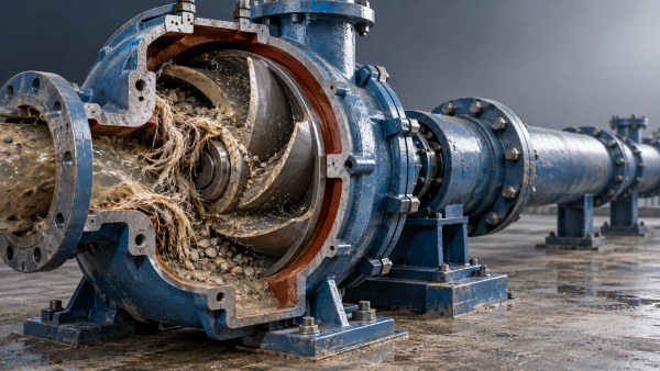
- Fibers wrapped around the impeller or shaft area: investigate stringy feed material and features where it can catch.
- Coarse particles wedged at the inlet or impeller eye: compare actual particle shape and size with the smallest available opening.
- A compacted bed in a horizontal pipe: investigate settling, line velocity, and shutdown practices.
- Dense material throughout the casing: investigate concentrated feed, loss of agitation, or solids settling during a stop.
- Little obstruction inside the pump: continue checking suction conditions, valves, piping, wear, and available pump head.
Pressure readings, flow trends, motor current, sump level, and speed are most useful when compared with normal operation at a similar slurry condition. Motor current alone cannot reliably locate a blockage: its response depends on the pump curve, slurry properties, and the type of restriction.
Why do solids that appear small enough still cause plugging?
Particle shape and occasional oversize material change the problem
An average particle size can hide the material responsible for repeated failures. A process may produce mostly fine solids while occasionally releasing stones, hardened deposits, metal fragments, or pieces of liner. These infrequent objects can determine whether the pump remains available.
Examine the largest credible incoming object and the narrowest point along its route. The limiting opening may be a suction fitting, reducer, valve, or strainer rather than the pump itself. Several particles can also bridge together, particularly where the flow changes direction or an opening narrows.
If oversize material is confirmed, screening or upstream separation may be appropriate. That equipment must have a practical cleaning method and sufficient capacity for the feed. An undersized screen simply moves the blockage upstream and can restrict the pump’s supply.
Fibers behave differently from granular solids
Textile strips, plastic film, roots, and other flexible debris can fold through an opening and then wrap around a rotating component. Once a small bundle catches, it can collect additional fibers and trap mineral particles. The resulting obstruction may be much larger than any individual item entering the pump.
A larger spherical passage does not necessarily solve this mechanism. Review the pump’s suitability for the actual fibrous material, including its length and tendency to form bundles. Where cutting or chopping equipment is considered, assess its compatibility with abrasive solids and hard contaminants; a cutting mechanism introduces its own wear and maintenance requirements.
The feed can become harder to pump without looking very different
Higher solids concentration can increase flow resistance and make transport less stable. Some fine-particle slurries develop yield stress, so their behavior differs substantially from water carrying freely settling grains. Changes in process chemistry, temperature, or residence time can also alter how readily material flows.
A pump may therefore run successfully on the normal mixture and plug when a hopper releases a dense slug or an agitator stops. Samples taken only during steady production can miss this event. Compare normal feed with conditions immediately before a blockage, including concentration, coarse solids, and any interruption to mixing or dilution.
Can low flow make a non-clog pump block?
Yes. The pump must pass solids, and the system must keep those solids moving. In settling slurries, inadequate transport velocity allows particles to accumulate along the bottom of a pipe. The deposit reduces the available flow area and increases resistance, which can reduce flow further and encourage additional settling.
There is no single minimum velocity suitable for every slurry. The requirement depends on particle size and density, solids concentration, liquid properties, pipe diameter, and route. A value borrowed from another installation may be unsuitable, especially when the material or pipe size differs.
This explains why a larger discharge pipe can sometimes worsen plugging. At the same volumetric flow, increasing pipe diameter lowers average velocity. The larger pipe may reduce friction losses while making it harder to keep coarse particles in motion. Pipe sizing needs to account for both effects.
Operation well below the pump’s intended flow range can also promote internal recirculation and uneven solids movement. A partly closed discharge valve, increased downstream pressure, reduced speed, or accumulated pipe deposits may shift the operating point into an unfavorable region.
Check actual flow, head, and speed against the pump’s performance information and recommended operating range. Allow for the slurry’s effect on performance and for wear. Simply increasing speed can create excessive wear, power demand, or suction difficulties; establish what changed in the system before adjusting it.
Why does blockage happen after shutdown or at certain sump levels?
Blockage timing often reveals more than blockage frequency. A pump that plugs mainly on restart may have adequate running passages but poor control of settled solids. Material can settle in the casing, suction line, or discharge line during a stop. Restarting then requires the pump to mobilize a concentrated deposit as well as establish normal flow.
Where compatible with the process, a planned shutdown may include stopping the solids feed and flushing the pump and line before stopping flow. The flushing arrangement must reach the sections where deposits form, with enough flow and duration to clear them. A brief addition of water to the sump does not demonstrate that a long discharge line has been cleared.
Emergency stops need separate consideration because the normal flushing sequence may be unavailable. Depending on the installation, useful measures can include drainable piping, accessible cleanout points, or an engineered restart procedure. Repeated attempts to start against a packed obstruction can damage equipment without clearing the line.
If plugging follows a low sump level, inspect submergence and the possibility of air entrainment or vortex formation. An unstable supply can interrupt transport and allow solids to accumulate. If it follows a high level or long idle period, examine whether settled material is entering the suction as a dense mass.
Sump agitation also needs to suit the feed and geometry. Mixing can help maintain a more uniform concentration, but poorly positioned agitation may leave dead zones or entrain air near the suction. The relevant observation is whether the pump receives a consistent, pumpable mixture through the full operating cycle.
Could wear or maintenance changes be contributing?
A worn impeller can lose enough hydraulic performance to reduce line velocity and encourage deposition, even if its passages remain open. Damaged edges, rough surfaces, and incorrectly adjusted clearances can also change internal flow or provide places for flexible debris to catch.
When blockages begin after maintenance, compare the installed configuration with the approved arrangement. Check impeller selection, rotation, speed settings, clearances, and valve positions. Replacement components should match the service requirements; a part that physically fits may have different hydraulic characteristics.
When plugging becomes gradually more frequent, compare the trend with wear measurements and performance records. Falling flow at similar speed and operating conditions can help distinguish progressive hydraulic deterioration from a sudden change in feed material.
What should you change first?
Choose the corrective action that matches the recovered material and operating pattern. Oversized debris points toward feed control or passage suitability. Fiber bundles point toward material handling and impeller geometry. Settled pipe deposits point toward transport conditions and shutdown management. Dense slugs point toward feed consistency, mixing, and concentration control.
For a useful review with the pump supplier or process engineer, assemble the pump model and impeller details, pipe layout and elevations, normal and minimum flow, speed, available pressure readings, slurry characteristics, and photographs of the obstruction. Include the event timing: during steady running, after a feed change, at low sump level, or on restart.
A replacement pump becomes a stronger option when the required solids passage, fiber handling capability, wear resistance, or operating range lies beyond the installed design. Specify the difficult credible condition as well as the normal duty. A pump selected only around average flow and average particle size can repeat the same failure.
After making a change, evaluate it through the conditions that previously triggered plugging, including relevant shutdown and restart cycles. Reliable operation means maintaining transport through those conditions. A short run on clean water cannot establish that the slurry blockage has been resolved.
Related Information
 Oct 31, 2026
Why Does a Non-Clog Slurry Pump Still Get Blocked?
Why does my non-clog slurry pump still block up? Discover how debris, settling, low flow, and wear cause blockages—and find practical fixes to reduce downtime.- Oct 31, 2026
Can a Standard Slurry Pump Run Continuously at 120°C?
Can a standard slurry pump run continuously at 120°C? Discover critical seal, material, and suction requirements—and learn what to verify before approving continuous hot-slurry service. - Oct 30, 2026
Do Slurry Pumps Handling Flammable Hydrocarbons Need Double Seals?
Does a slurry pump handling flammable hydrocarbons need a double mechanical seal? Explore leakage risks, seal options, and barrier systems to choose safer, more reliable containment. - Oct 30, 2026
How Can You Tell When a Slurry Pump Liner Needs Replacing?
How do I tell when a slurry pump liner needs replacing? Learn key wear signs, thickness limits, and inspection tips to plan replacement, protect your pump, and avoid costly downtime.

{item.title}
Get a Quote
Please leave your information and email address, and we will contact you as soon as possible.