
How Do You Replace a Slurry Pump Bearing Assembly?
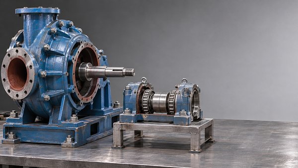
Replacing a slurry pump bearing assembly involves isolating and draining the pump, disconnecting the drive, supporting and removing the rotating assembly, then fitting a compatible replacement and checking alignment, lubrication, and impeller clearance before restart. The exact removal sequence depends on the pump design: some assemblies can be exchanged as complete cartridges, while others require more extensive dismantling.
Before starting, establish whether the bearings are actually the source of the problem and obtain the pump manufacturer’s procedure for the specific model. Slurry pumps are heavy, often handle hazardous material, and can retain pressure or liquid after shutdown. A bearing replacement should be carried out by trained personnel with suitable lifting equipment and access to the correct adjustment and torque specifications.
When should the bearing assembly be replaced?
Excessive vibration, rising bearing housing temperature, unusual noise, lubricant leakage, or noticeable shaft movement can justify an investigation. Contaminated grease or oil, metal particles in lubricant, and recurring seal problems may also point toward bearing or shaft damage.
These symptoms do not prove that the bearing assembly has failed. A blocked impeller, worn wet-end components, loose foundation bolts, coupling misalignment, or unsuitable operating conditions can produce similar signs. If the pump is still safe to operate, compare vibration and temperature readings with its established operating history and inspect the drive and lubrication system before deciding on the repair.
Stop the equipment under site procedures if there are signs of imminent failure, such as severe noise, rapidly increasing temperature, or substantial shaft movement. Continuing to run a damaged assembly can affect the shaft, housing, seals, and other components, making the repair more extensive.
What should be checked before dismantling?
Confirm the pump model, serial number, shaft arrangement, drive type, and bearing assembly configuration. A replacement that looks similar may differ in shaft dimensions, bearing arrangement, lubrication method, mounting features, or impeller adjustment mechanism. Check the replacement against the manufacturer’s parts information and the assembly being removed.
Also determine the scope of work. A complete replacement assembly may arrive with the shaft, bearings, housing, and seals assembled, but its lubrication and installation requirements still need checking. If only the bearings are being replaced within the existing housing, the job may require controlled heating, pressing equipment, bearing clearance checks, and a clean assembly area. That work should follow the bearing and pump manufacturers’ instructions.
Before shutdown, have the following available:
- The model-specific dismantling, installation, lubrication, and alignment instructions.
- A verified replacement assembly and the required gaskets, seals, locking devices, and fasteners.
- Rated lifting equipment, suitable lifting points, and supports for the pump and drive components.
- Tools for the specified fastener torque, coupling alignment, shaft movement checks, and impeller adjustment.
- Suitable containers and protective equipment for residual slurry, flush liquid, and lubricant.
Plan for the weight and balance of the components before removing fasteners. Do not assume that a lifting eye on one part is rated to support the entire pump or an attached drive.
How do you remove the old assembly?
1. Isolate, depressurize, and drain the pump
Shut down the pump using the site procedure. Isolate and lock out all energy sources, including the motor and any auxiliary systems that could cause movement or introduce pressure. Verify isolation before working on the equipment. Close and secure the relevant process lines, relieve trapped pressure, and drain and flush the pump as required for the material handled.
Slurry can settle and block a drain while liquid remains inside the casing. Open the equipment cautiously under the site’s hazardous-material controls, and be prepared for residual material in the casing, seal chamber, and connected pipework.
2. Remove guards and disconnect the drive
Remove the coupling or belt guards and record the drive arrangement. Disconnect the coupling, belts, or other drive components in the sequence specified for the equipment. Mark useful reference positions and retain any shims in an identified location, but do not assume that the original alignment will be correct after the replacement is installed.
Disconnect lubrication lines, cooling lines, instrumentation, or other connections attached to the assembly. Protect open lines and ports from dirt. Support the drive and pump components independently wherever the procedure requires it.
3. Expose and withdraw the rotating assembly
The next steps vary considerably. Depending on the design, removal may involve the casing, suction-side components, impeller, shaft sleeve, gland, or mechanical seal. Some pumps allow a rotating assembly to be withdrawn from the drive end; others require a different sequence. Follow the model-specific procedure, especially for impeller removal and threaded components.
Take note of the impeller clearance setting and the position of adjustment hardware where accessible. These observations can help with reassembly, but the final setting must be made to the specified procedure. Support the bearing assembly with rated lifting equipment before removing its mounting or retaining fasteners, then withdraw it without allowing the shaft to strike the casing or seal surfaces.
Do not hammer on the shaft, bearing housing, or impeller to free a stuck component. Use the prescribed extraction points and tools. If corrosion, hardened slurry, or damaged threads prevent removal, reassess the method before applying additional force.
What should be inspected while the pump is open?
Clean accessible parts and examine the bearing housing mounting surfaces, shaft, shaft sleeve, seal components, coupling, and impeller for wear or damage. Look for scoring, corrosion, cracks, loose fits, and evidence that slurry or washdown water has entered the bearing housing. Check the condition of the adjustment mechanism and any bearing housing seals or deflectors.
Inspect the casing and wet-end wear surfaces as well. A replacement bearing assembly will not correct damage caused by an impeller rubbing against a liner, a compromised shaft seal, or a blocked lubrication path. Replace or repair affected parts according to the manufacturer’s limits and site procedure.
Preserve evidence of the old failure where practical. Contaminated lubricant may point toward ineffective sealing; overheated or damaged components may warrant a closer look at lubrication, alignment, loading, or assembly condition. Avoid assigning a cause from one symptom alone. If failures have recurred, a more detailed examination of the bearings and operating conditions can help prevent the replacement from suffering the same fate.
How is the new bearing assembly installed?
Confirm that the replacement is clean, undamaged, and configured for the pump. Check whether it was supplied lubricated, protected with a preservative, or intended to be filled after installation. Use the specified lubricant and quantity; both insufficient and excessive lubrication can cause problems. Do not mix lubricants unless their compatibility has been established.
Lift the assembly using its approved lifting points and position it on clean, undamaged mounting surfaces. Keep protective covers in place until they interfere with installation, and prevent dirt or moisture from entering open bearing or seal areas. Fit the specified fasteners and locking devices, and tighten them in the required sequence to the manufacturer’s torque values.
Reinstall the shaft sleeve, seal components, impeller, casing parts, and other items in the order specified for the pump. Seal installation deserves particular care: protect sealing faces from damage, use the required elastomers and installation materials, and check that any flush or cooling connections are correctly reinstated. A new bearing assembly can be damaged if a seal leak subsequently allows slurry or water into the housing.
Set the impeller clearance
Many slurry pumps have an adjustable clearance between the impeller and an adjacent wear surface. The correct setting and adjustment method depend on the pump and liner design. Use the manufacturer’s procedure and account for the direction of adjustment, any specified reference position, and the effect of tightening locking fasteners.
Too little clearance can cause rubbing; too much can reduce pump performance. Do not use a generic clearance value or rely solely on the position of the old adjustment hardware. Once set, secure the adjustment mechanism and check that the shaft rotates freely by the method permitted in the procedure.
Align the drive
Reconnect the coupling or belts and align the drive to the equipment manufacturer’s requirements. For a coupled drive, check alignment in the required planes and correct it using appropriate methods and shims. For a belt drive, check sheave alignment and belt tension to the drive specifications.
Alignment should be checked after the assembly is mounted and adjusted, because its position may have changed. Complete any required final checks with the coupling connected, and refit all guards before the equipment is returned to service.
What should be checked before and after restart?
Before starting, verify that tools and lifting gear have been removed, fasteners and guards are secure, and all lubrication, seal flush, cooling, and instrumentation connections are restored. Confirm that the pump is properly filled or primed as required, valves are in their intended positions, and the system is ready to receive flow. Never assume a slurry pump can run dry without damage.
Verify the direction of rotation using the manufacturer’s approved procedure. Some impeller and coupling arrangements can be damaged by reverse rotation, so do not improvise a rotation check with the pump fully assembled. Once the checks are complete, remove isolations under the site’s authorization process and start the pump.
Observe bearing housing temperature, vibration, noise, seal leakage, lubricant leakage, and operating conditions during the initial run. Temperature may change as the assembly settles into operation, but a rapid rise, severe vibration, rubbing, or unexpected leakage calls for shutdown and investigation under the site procedure. Record the initial readings and compare them with subsequent readings under similar operating conditions.
After the prescribed run-in period, carry out any manufacturer-required checks of fasteners, lubrication, alignment, and impeller adjustment. Close the work order with the parts installed, lubricant used, clearance and alignment results, and observations about the removed assembly. Those records give the maintenance team a useful reference if the symptoms return.
Related Information
 Nov 09, 2026
How Do You Replace a Slurry Pump Bearing Assembly?
Slurry pump bearing assembly replacement made clear: explore safe removal, installation, alignment, lubrication, and restart checks to help reduce downtime.- Nov 09, 2026
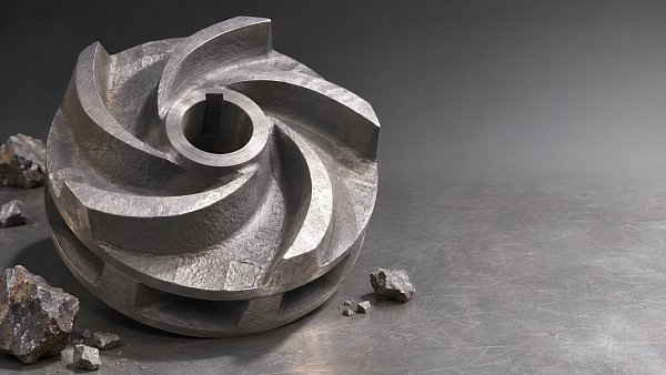
Do High-Chrome Pump Parts Resist Coarse, Sharp Particles?
Will high chrome pump parts resist wear from coarse, sharp particles? Explore their abrasion resistance, impact limits, and how to select the right material for your slurry. - Oct 31, 2026
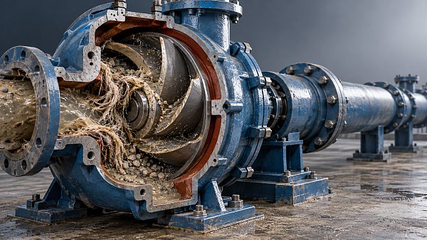
Why Does a Non-Clog Slurry Pump Still Get Blocked?
Why does my non-clog slurry pump still block up? Discover how debris, settling, low flow, and wear cause blockages—and find practical fixes to reduce downtime. - Oct 31, 2026
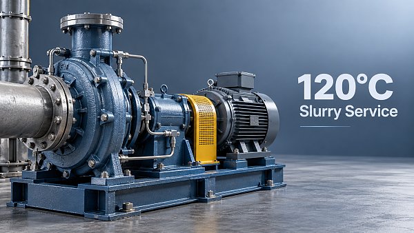
Can a Standard Slurry Pump Run Continuously at 120°C?
Can a standard slurry pump run continuously at 120°C? Discover critical seal, material, and suction requirements—and learn what to verify before approving continuous hot-slurry service.

{item.title}
Get a Quote
Please leave your information and email address, and we will contact you as soon as possible.