
Industrial Knife Gate Valves fail in ways fundamentally different from low-cost alternatives—not because of isolated component breakdowns, but due to how design margins, material selection, and structural integration respond under real-world service conditions. When a valve leaks, sticks, or loses actuation precision, the root cause is rarely identical across product tiers. Understanding these distinctions requires looking beyond surface symptoms and into the interplay between load path integrity, seat retention mechanics, and blade-to-frame interface behavior.
Seat Extrusion: Not Just Wear—It’s a Design Boundary Failure
Low-cost valves often use elastomeric seats bonded to simple metal carriers. Under sustained line pressure—especially above 150 psi—or with abrasive slurry flow, the elastomer deforms radially into gaps between the carrier and body cavity. This extrusion isn’t gradual wear; it’s a mechanical yield event triggered by insufficient radial confinement and inadequate support geometry. Industrial-grade valves counter this with machined seat pockets that precisely control lateral movement, hardened steel backing plates that resist deflection, and dual-durometer elastomers where a stiff outer layer resists extrusion while a softer inner layer maintains seal conformity. Crucially, the seat mounting interface is designed so that pressure forces compress—not pull apart—the seat assembly. In budget units, pressure often acts to *pry* the seat away from its mounting surface, accelerating failure even at moderate pressures.
Blade Warping: Thermal & Mechanical Load Distribution Matters
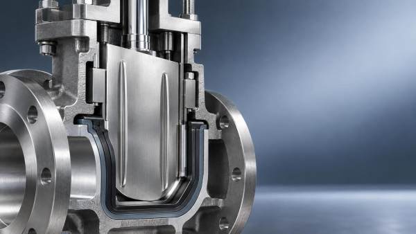
A warped blade doesn’t always mean poor heat treatment. In industrial Knife Gate Valves, blade flatness is maintained through balanced thermal mass distribution and controlled stress-relief machining. Low-cost alternatives frequently use thinner blades with non-uniform cross-sections—thicker near the stem, tapering sharply toward the cutting edge. During repeated cycling, especially with temperature swings or high-viscosity media, differential expansion creates internal bending moments. The result isn’t uniform bowing—it’s localized twisting near the blade tip, causing uneven seat contact and premature leakage along one side. Industrial blades are engineered with symmetrical stiffness profiles and often incorporate integral stiffening ribs aligned perpendicular to flow direction. These ribs don’t just add strength—they redirect bending stresses into axial compression, which the stem and actuator are designed to absorb without misalignment.
Actuator Misalignment: Frame Rigidity Dictates Long-Term Tracking
Misalignment isn’t solely an installation issue. It becomes self-reinforcing when the valve frame lacks torsional stiffness. Budget valves commonly use thin-walled cast housings with minimal ribbing. Under cyclic torque loading—even within nominal actuator specs—the frame flexes, shifting the stem axis relative to the seat plane over time. Each cycle compounds the angular deviation, leading to asymmetric blade loading, accelerated seat wear on one side, and eventual stem binding. Industrial frames use thicker wall sections, strategically placed gussets, and sometimes welded steel construction instead of casting alone. More importantly, the stem-to-frame interface includes dual-bearing support: a top-mounted thrust bearing for axial loads and a lower radial guide bushing that maintains concentricity during full travel. This dual-point constraint prevents the “wobble” effect common in single-bearing designs, preserving alignment across thousands of cycles—even with high-torque actuators.
Stem Corrosion & Galling: Surface Finish and Material Pairing Are Non-Negotiable
Corrosion on the stem isn’t always environmental—it’s often galvanic or tribological. Low-cost valves may pair stainless steel stems with aluminum or zinc-plated yokes. In humid or washdown environments, micro-galvanic cells form at the interface, accelerating pitting beneath the packing. Worse, many budget stems use 304 stainless with standard mill finish (Ra > 0.8 µm). When paired with generic PTFE-based packing, the rough surface increases friction, promotes cold welding (galling), and causes packing extrusion under cycling. Industrial-grade valves specify stem materials matched to housing metallurgy—e.g., 17-4PH H900 heat-treated stems with hardened 416 stainless yokes—and require mirror-finish grinding (Ra ≤ 0.2 µm) combined with proprietary packing formulations that embed lubricating solids. The result isn’t just corrosion resistance—it’s stable friction coefficients across temperature and cycle count.
Seal Leakage Patterns Reveal Root Cause Faster Than Pressure Testing
Where leakage occurs tells more than whether it leaks. Consistent leakage along the entire blade perimeter suggests seat extrusion or frame distortion. Leakage concentrated at the blade tip—especially if worse in open position—points to torsional frame flex or blade twist. Leakage only when closing against high differential pressure indicates inadequate seat retention geometry. Leakage that worsens after 50–100 cycles but stabilizes points to initial break-in of mismatched materials; leakage that progressively worsens cycle after cycle signals progressive deformation—often tied to underspecified frame stiffness or improper thermal relief design. Industrial valves are validated not just for leak rate, but for *leak location consistency* across 10,000+ cycles under representative duty profiles. That consistency reflects integrated design—not just component quality.
Material Interfaces Define Service Life—Not Just Individual Components
A common misdiagnosis is attributing failure to “bad elastomer” or “weak casting.” In reality, most premature failures stem from incompatible interfaces: a high-durometer seat pressed against a soft-bodied frame; a hardened blade sliding against an unhardened guide rail; or a stainless stem rotating inside a bronze bushing with no controlled clearance. Industrial Knife Gate Valves define tolerances and hardness differentials across *all* sliding and sealing interfaces—not per part, but per functional pair. For example, guide rails are induction-hardened to 58–62 HRC, while mating blade surfaces are ground to match that hardness profile within ±2 HRC. This eliminates preferential wear and ensures wear rates remain proportional across the system. Budget valves rarely specify such pairings—leading to rapid degradation of the softer component, even if its standalone specification appears adequate.
The distinction between industrial and low-cost Knife Gate Valves isn’t measured in price or brand—it’s encoded in how each component’s behavior is anticipated, constrained, and balanced within the complete mechanical system. Recognizing failure modes means reading the symptom not as an endpoint, but as evidence of where that balance broke down—and whether the design ever intended to sustain it.
 Sep 18, 2026What failure modes distinguish industrial knife gate valves from low-cost alternatives?Knife Gate Valves: Discover how industrial-grade knife gate valves fail *differently*—and why design integrity, not just price, defines true reliability.
- Sep 17, 2026Can zero leakage knife gate valves eliminate fugitive emissions in tailings transfer lines?Zero Leakage Knife Gate Valves—engineered to eliminate fugitive emissions in tailings transfer lines. Discover how true zero-leak design, proper installation & active maintenance deliver measurable safety and compliance gains.
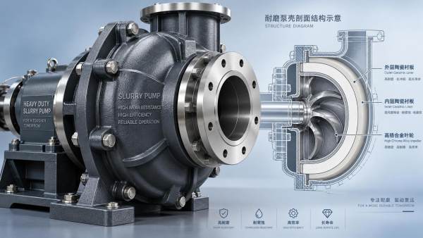
- Sep 16, 2026When do wear resistant slurry pumps justify higher upfront cost over standard models?Wear Resistant Slurry Pumps deliver ROI in 6–18 months for high-erosion, continuous-duty applications—cut downtime, extend service life, and slash TCO.
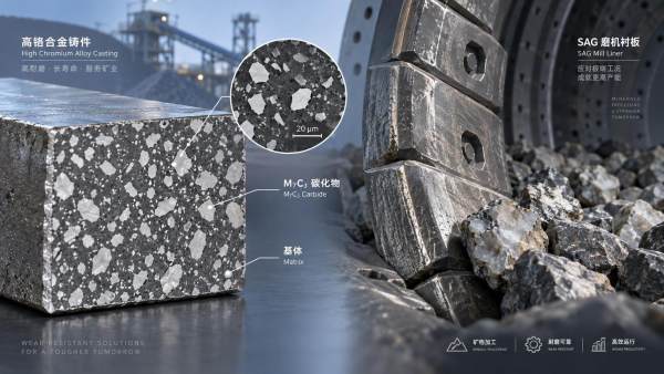
- Sep 14, 2026How do high chrome alloy castings perform in abrasive mineral processing environments?High Chrome Alloy Castings deliver exceptional wear resistance in abrasive mineral processing—discover how microstructure, heat treatment, and real-world conditions drive true service life.

Get a Quote
Please leave your information and email address, and we will contact you as soon as possible.