
How Do You Adjust Slurry Pump Impeller Clearance?
Proper slurry pump impeller clearance adjustment helps maintain pumping efficiency, reduce wear, and prevent contact between the impeller and casing. As components wear during operation, the clearance can change, affecting flow and performance. Knowing when and how to adjust it can help operators avoid unnecessary downtime and extend equipment life. This guide explains the adjustment process, essential safety precautions, and practical checks to help you restore the correct clearance according to your pump manufacturer’s specifications.
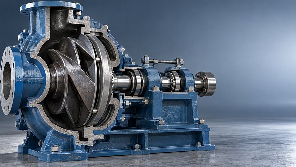
In many centrifugal slurry pumps, clearance is adjusted by moving the shaft and impeller axially relative to the casing or wear liner. The method depends on the pump design: some use an external bearing assembly adjustment, while others rely on shims or a different arrangement. The correct setting is not universal, and the reference surface matters as much as the number itself.
What Clearance Are You Adjusting?
Impeller clearance is the axial gap between a rotating impeller surface and an adjacent stationary surface. Depending on the pump, the relevant surface may be a front liner, suction-side wear plate, casing component, or another specified wear face. Some designs also require attention to the clearance at the rear of the impeller.
That distinction is easy to overlook. Moving an impeller toward one side generally changes the gap on the opposite side as well. A setting that looks reasonable at the suction side can therefore create contact elsewhere if the assembly is worn, incorrectly fitted, or adjusted using the wrong reference. Follow the manufacturer’s procedure for the exact pump and impeller configuration rather than applying a setting borrowed from a similar unit.
When clearance becomes excessive, more liquid can recirculate internally rather than contributing to useful discharge flow. Wear at the impeller and liner may make that gap larger over time. Conversely, too little clearance can cause rubbing as parts deflect or temperatures change. The resulting damage may extend beyond the wear components to the shaft, bearings, or drive.
Before Touching the Adjustment Mechanism
Treat this as work on both a rotating machine and a potentially hazardous process system. Stop the pump and isolate all energy sources under the site’s lockout and tagout procedure. Depending on the installation, that may include electrical, hydraulic, pneumatic, or other stored energy. Verify zero energy and secure the rotor against unexpected movement where required.
Isolate the pump from the process, relieve pressure, and drain or flush the casing as required by site procedures. Consider the slurry itself: hot, corrosive, toxic, or settling solids can create hazards even after the motor is stopped. Confirm that isolation valves are suitable for the duty and that any trapped liquid has a safe discharge path. Use the specified protective equipment.
Collect the pump model and serial number, the applicable manual, the installed impeller and liner details, and the current maintenance record. Check whether the instructions specify a cold setting, a particular measurement point, a torque value, or a sequence for loosening and tightening fasteners. If the unit has been modified or contains non-original wear parts, verify which instructions apply before proceeding.
How to Adjust the Impeller Clearance
The following sequence describes the decisions involved, not a substitute for the pump-specific manual. Adjustment hardware and measurement methods vary, and the wrong direction of movement can bring the impeller into contact with a liner.
1. Establish the Starting Condition
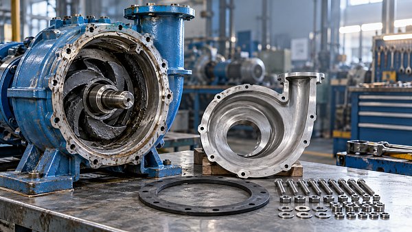
Inspect the accessible adjustment hardware for damage, corrosion, loose fasteners, and signs of previous movement. Mark or record the existing bearing assembly position or shim arrangement so there is a reliable reference. Note relevant operating symptoms, such as reduced flow at a comparable speed, rising vibration, or a change in suction pressure.
Where the manufacturer provides a measurement method, check the existing clearance or axial position before making changes. A dial indicator, feeler gauge, or movement measured through the adjustment mechanism may be appropriate, depending on access and design. Do not assume that a turn of an adjusting screw corresponds to a particular movement without confirming the thread and arrangement in the manual.
2. Release the Specified Fasteners and Move the Assembly
Loosen only the fasteners identified in the pump instructions. Some arrangements move the bearing housing and shaft as an assembly; others use shims to establish position. Support components where the procedure requires it, and make small, controlled changes. Keep the assembly aligned and avoid forcing a seized adjuster, since damage to the threads or housing can turn a routine correction into a larger repair.
Some manufacturer procedures use a carefully established contact position as a reference before moving the impeller back by a specified amount. Others require direct measurement or a different reference. Use contact only when the applicable procedure explicitly calls for it, and never use motor power to establish that point. If the rotor cannot be moved safely by the approved method, stop and investigate rather than applying additional force.
3. Set, Secure, and Recheck
Move to the specified operating clearance using the prescribed reference and measurement method. Take up any adjustment mechanism slack in the direction required by the manufacturer; otherwise, the indicated movement may not represent the actual final position. Tighten locking and mounting fasteners in the specified sequence and to the specified torque.
Recheck the setting after tightening. Locking the assembly can change its position slightly, especially if fasteners were tightened unevenly. Where the design permits and site procedure allows, turn the shaft by the approved manual method to check for free rotation and any indication of rubbing. Keep hands and tools clear of pinch points. Free rotation is a useful check, but it does not replace the specified clearance measurement.
Record the final setting, measurement method, adjustment made, and any unusual observations. A clear record gives the next maintenance crew a starting point and helps distinguish normal wear progression from an assembly that repeatedly moves out of position.
Restart Checks That Reveal More Than a Clearance Reading
Before returning the pump to service, restore guards, close drains, remove tools, and return the system to its approved operating configuration. Confirm that the pump is properly primed or flooded as required. Follow the site’s startup procedure and the manufacturer’s instructions for seal water or other auxiliary systems.
Once operating conditions have stabilized, compare flow, suction and discharge pressures, motor current, vibration, and bearing temperature with reliable records taken under similar conditions. Listen for new rubbing or unusual noise. A change in process conditions can affect these readings, so a comparison is meaningful only when speed, slurry characteristics, and system configuration are reasonably comparable.
Stop and investigate if there are signs of contact, abnormal vibration, overheating, or leakage. Do not attempt to correct a suspected rubbing condition by adjusting the assembly while the pump is running unless the manufacturer explicitly permits that method and the site has an approved procedure for it.
When Adjustment Will Not Solve the Problem
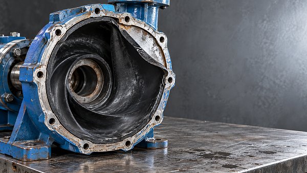
Clearance adjustment can compensate for some wear; it cannot restore material that has disappeared from the impeller vanes or liner. If the required setting cannot be reached within the permitted adjustment range, or if performance deteriorates again quickly, inspect the wear parts and the adjustment mechanism. Uneven wear, a damaged liner, a loose impeller, or excessive shaft movement may require repair rather than another turn of the adjuster.
Poor pump performance can also originate outside the clearance itself. Blocked suction passages, air ingress, insufficient suction conditions, an obstructed discharge line, incorrect rotation, and changes in slurry concentration or particle size can produce symptoms that resemble internal wear. Checking these possibilities before repeated adjustments avoids masking the real fault.
If the pump has recurring contact after a correct cold setting, examine the full assembly and operating conditions. Bearing condition, shaft deflection, thermal movement, incorrect parts, and liner seating are all worth investigating. The appropriate running clearance must accommodate the behavior of that particular design; making the gap smaller simply because flow is low is not a sound maintenance strategy.
How Often Should Clearance Be Checked?
There is no useful interval that fits every slurry service. Abrasiveness, particle size, concentration, operating speed, materials, and duty cycle all affect wear. Start with the manufacturer’s maintenance recommendations, then use inspection findings and operating trends to establish an interval suited to the installation.
A drop in flow or discharge pressure can justify a check, but neither confirms excessive clearance on its own. Compare readings against a known operating baseline and look for changes in suction conditions or the downstream system. During planned shutdowns, document both the measured position and the condition of accessible wear parts; together they are more informative than an adjustment count alone.
Before the next intervention, make sure the maintenance team has the correct manual, the specified clearance reference, and a way to verify the final position after fasteners are secured. If those details are unclear, confirm them with the pump manufacturer or a qualified service provider before moving the assembly. That is a better use of downtime than guessing at a gap and discovering the mistake on restart.
Related Information
 Nov 04, 2026
How Much Does Slurry Pump Liner Replacement Cost?
Slurry pump liner replacement cost depends on parts, labor, freight, and downtime. Learn how to compare quotes and budget for long-term value.- Nov 04, 2026
How Do You Adjust Slurry Pump Impeller Clearance?
Slurry pump impeller clearance adjustment made clear: discover safe, practical steps to maintain efficiency, reduce wear, and avoid costly downtime. - Nov 03, 2026
Why Is Your Slurry Pump's Rubber Liner Peeling?
Can sharp particles cause slurry pump liner peeling? Discover the warning signs, other possible causes and practical steps to prevent repeat failures. - Nov 03, 2026
Can High-Chrome Pump Parts Resist Coarse, Sharp Particles?
Will high chrome pump parts resist wear from coarse, sharp particles? Discover their limits and learn how to select the right alloy for your slurry pump.


{item.title}
Get a Quote
Please leave your information and email address, and we will contact you as soon as possible.