
How to Adjust Impeller Clearance on a Worn Slurry Pump
How to Adjust Impeller Clearance on a Worn Slurry Pump
Knowing how to adjust impeller clearance on a worn slurry pump correctly is essential for restoring hydraulic efficiency, reducing internal recirculation, and extending the working life of expensive wet-end parts. In abrasive slurry service, clearance does not remain fixed for long. The impeller, throatbush, suction liner, side liners, and casing components gradually wear, increasing the path through which slurry can leak back from the high-pressure side to the low-pressure side.
That internal leakage may look minor on paper, but it can quickly affect head, flow stability, power draw, and the pump’s ability to stay near its intended operating point. Maintenance teams often respond by increasing speed or opening valves further. Those actions may keep production moving temporarily, yet they do not address the actual cause. Where the pump design permits it, resetting the impeller position is usually the more sensible first step.
The adjustment itself is not difficult in principle. The challenge is recognizing what has worn, identifying which clearance matters, and avoiding an adjustment that creates metal-to-metal contact once the pump heats up or sees a change in duty. A slurry pump is not a precision laboratory device, but it does need controlled running clearance. “As tight as possible” is not always the correct target.
Why clearance changes pump performance
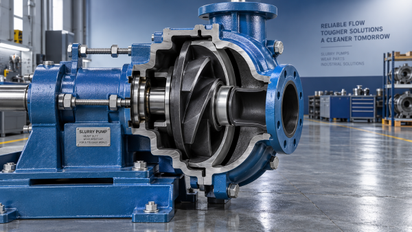
Most horizontal slurry pumps use an impeller positioned close to a suction-side component, often called a throatbush or throatbush liner depending on the design. As this interface wears, the gap grows. The pressure difference across the impeller encourages slurry to recirculate through that gap rather than moving through the discharge line. The pump may still rotate smoothly and appear mechanically sound, while its hydraulic performance falls away.
This is especially noticeable in duties with coarse solids, high specific gravity, or intermittent operation. Abrasive particles enlarge clearances unevenly. A worn impeller may lose material at its vane tips, shrouds, and eye; a liner may wear concentrically, ovally, or in localized zones where the slurry flow is most aggressive. Moving the impeller forward can compensate for some axial wear, but it cannot restore a severely eroded vane profile or a badly damaged liner.
The practical question is not simply whether clearance has increased. It is whether adjustment can return the pump to stable service without creating excessive rubbing, vibration, or premature failure of the remaining wet-end components.
Confirm the pump arrangement before touching the adjuster
Slurry pump designs differ substantially. Many horizontal pumps use a bearing assembly with an external adjustment mechanism that shifts the shaft and impeller axially. Depending on the manufacturer and frame arrangement, this may be a jacking screw, a threaded bearing cartridge, adjustment bolts, a clamp arrangement, or a combination of screws and locking hardware. Some pumps are adjusted from the drive end; others provide access near the bearing housing.
Vertical sump pumps, submersible slurry pumps, and certain cartridge-style units may not offer the same field adjustment. Closed impellers and open impellers also behave differently. An open impeller may require a controlled clearance to a side liner, while a closed impeller may be governed primarily by the relationship between the impeller inlet and throatbush. Never assume that a procedure used on one pump family is suitable for another, even when the pumps appear similar.
Before adjustment, obtain the pump’s drawing, maintenance manual, or the original equipment manufacturer’s recommended setting method. The correct cold clearance, the direction of impeller movement, and the allowable adjustment travel are design-specific. If the documentation is unavailable, record the existing position carefully and inspect the wetted components before attempting to improve performance through adjustment alone.
Inspect first: adjustment cannot repair every wear pattern
A pump that has lost duty may have excessive impeller clearance, but it may also have air ingress, a blocked suction strainer, a worn suction pipe, a damaged seal, incorrect rotational speed, or a process change that has altered slurry density or particle size. Adjustment should follow a basic condition review, not replace one.
With the pump isolated and drained, examine accessible wet-end areas. Look for deep grooves in the throatbush, cracking in elastomer liners, broken or thinned impeller vanes, loss of expeller features, and uneven contact marks. Check the bearing assembly for excessive end float, abnormal noise history, overheating, and lubricant condition. If shaft movement is caused by bearing wear rather than an intended adjustment mechanism, tightening the hydraulic clearance may only conceal a mechanical problem for a short time.
A practical adjustment sequence
The exact hardware varies, but the adjustment logic is broadly consistent. Work under the site’s lockout, isolation, and slurry-handling procedures. Stop the pump, isolate electrical or mechanical power, close and secure relevant valves, relieve pressure, and allow the pump to cool where necessary. Slurry systems can retain pressure and hazardous material in pipework, so this is not a task to perform on an assumed “stopped” system.
1. Establish the existing condition
Mark the current adjuster position or measure the exposed thread length where that method is meaningful. Record any shims, locknut locations, or bearing housing references. This gives the maintenance team a recovery point if the new setting proves unsuitable. It also helps track how much of the original adjustment travel has already been consumed during the life of the wet end.
2. Release locking components
Loosen locknuts, clamps, or retaining bolts only as required by the pump design. Do not remove structural fasteners unnecessarily. On some assemblies, adjustment load is carried through a threaded bearing housing, while other arrangements use separate push and pull bolts. Forcing an adjuster against a locked component can damage threads or distort the intended setting mechanism.
3. Bring the impeller toward the suction-side wear component slowly
Move the impeller in the direction specified by the manufacturer, usually toward the throatbush or front liner when compensating for suction-side clearance. Use small, even movements. A large adjustment may produce contact before the operator has a clear sense of where the impeller is relative to the liner. If twin bolts are used, adjust them evenly so the shaft assembly is not cocked or stressed.
Rotate the shaft by hand during the process where safe and practical. The goal of this initial movement is generally to find the contact or near-contact reference point, not to leave the pump clamped against the liner. Resistance should be interpreted carefully. Slurry pumps with packed glands, mechanical seals, drive couplings, or residual solids may not turn freely for reasons unrelated to impeller contact.
4. Back off to the specified running clearance
Once the reference point is found, back the impeller away by the amount specified for that pump model and liner material. This is the point where generic advice becomes risky. A clearance suitable for one size of metal-lined slurry pump may be inappropriate for a rubber-lined pump, a high-speed unit, or a design with a different throatbush geometry. Use the original maintenance documentation whenever possible rather than relying on a remembered number from another installation.
The setting must account for real operating behavior: thermal expansion, shaft deflection, bearing condition, solids accumulation, and the possibility of uneven liner wear. A pump that turns freely while cold can still rub after startup if there is insufficient allowance.
5. Secure, verify, and monitor the restart
Tighten locking devices to the required condition, reinstall guards, and check coupling alignment if the adjustment method or bearing housing movement could affect it. During restart, listen for rubbing, watch vibration and bearing temperature trends, and confirm that discharge pressure or process performance responds as expected. Do not judge success by one indicator alone. Improved pressure accompanied by abnormal noise is not a successful adjustment.
The common mistake: adjusting until the pump rubs
A frequent field practice is to tighten the impeller forward until it touches, then reverse it slightly by feel. This can work only when the pump design, adjustment pitch, and required backing-off distance are well understood. It becomes unreliable where the liner is worn unevenly or the shaft has appreciable movement. A localized high spot may create contact long before the average clearance is correct.
Running with impeller contact can generate heat, accelerate wear, overload bearings, tear elastomer liners, and introduce vibration. In severe cases, it may damage the shaft sleeve, hub, or liner seating surfaces. The cost of replacing those parts is usually much higher than the time saved by a rough adjustment.
Another mistake is repeatedly advancing the impeller without documenting each adjustment. The team then loses visibility of wear progression. A simple maintenance record should include the date, observed performance issue, adjustment direction, approximate movement, wet-end condition, and post-adjustment observations. Over several shutdowns, that record helps determine whether the pump is seeing normal consumable wear or an abnormal duty condition.
When adjustment is no longer the right answer
Impeller clearance adjustment is a wear-compensation measure, not a permanent rebuild. If the impeller eye is heavily enlarged, vanes are thin or damaged, the throatbush has lost its profile, or the adjustment travel is nearly exhausted, replacing worn components is usually the sounder decision. Continuing to chase performance with progressively tighter settings may shorten the remaining service life and make the next repair more extensive.
It is also worth reviewing the duty when wear occurs faster than expected. Changes in particle size distribution, slurry concentration, pH, temperature, pump speed, suction conditions, or piping layout can all alter wear behavior. Material selection matters, but it should be considered alongside operating conditions. A harder alloy is not automatically the answer for every slurry, and an elastomer liner may be unsuitable where particles are sharp, oversized, or operating temperature is elevated.
A disciplined clearance check protects more than pump output
How to adjust impeller clearance on a worn slurry pump correctly comes down to controlled movement, inspection, and verification rather than force. Start with the pump’s specific arrangement. Confirm that the loss of performance is genuinely related to hydraulic wear. Establish a contact reference carefully, return to the documented running clearance, and watch the pump closely after restart.
When the required setting is uncertain, the safest next step is to confirm the pump model, wet-end configuration, liner material, and manufacturer’s adjustment procedure before work begins. That small amount of preparation can prevent liner damage, unplanned downtime, and the mistaken belief that a worn pump has been restored when it actually needs replacement parts.
Related Information
 Oct 11, 2026
What Causes a Slurry Pump to Clog During Operation?
What causes a slurry pump to clog during operation? Discover key causes, warning signs, and practical troubleshooting tips to reduce downtime and protect pump performance.- Oct 10, 2026
How Often Should Slurry Pump Impeller Clearance Be Adjusted?
How often should slurry pump impeller clearance be adjusted? Learn inspection intervals, wear indicators, and maintenance tips to improve pump efficiency and service life. - Oct 09, 2026
What Should Be Included in a Dredging Pump Quotation?
What should be included in a dredging pump quotation? Explore duty data, wear materials, drive packages, accessories, delivery terms, warranty, and testing for smarter buying.  Oct 11, 2026
How to Adjust Impeller Clearance on a Worn Slurry Pump
How to adjust impeller clearance on a worn slurry pump correctly: restore efficiency, reduce recirculation, and prevent costly wet-end damage.

Get a Quote
Please leave your information and email address, and we will contact you as soon as possible.