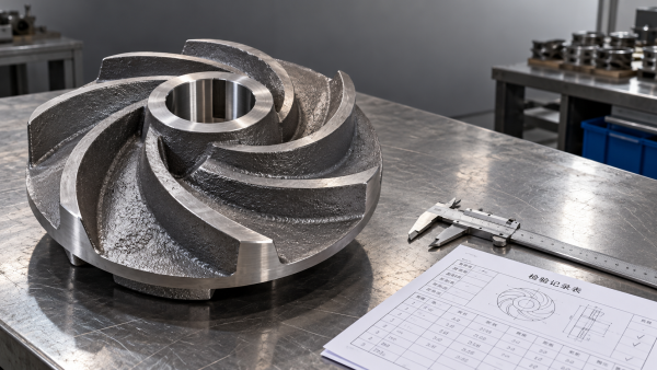
Sizing Froth Pumps for flotation circuits starts with two separate questions: how much aerated mixture reaches the pump, and how reliably can it handle that gas?
Matching slurry flow and discharge head alone can underestimate inlet volume while overlooking gas accumulation, unstable delivery, and reduced head generation inside the pump.
For technical evaluators, a defensible selection combines measured froth behavior, clearly defined flow calculations, realistic suction conditions, and supplier evidence covering the expected operating range.
What Must a Froth Pump Sizing Basis Actually Establish?
A useful sizing basis separates three quantities: gas-free slurry flow, aerated mixture flow at the inlet, and the hydraulic duty required by the discharge system.
Gas-free slurry includes liquid and solids. Aerated mixture flow additionally includes entrained gas, whose volume depends on local pressure, temperature, and the froth’s behavior.
The pump must accommodate the inlet mixture while generating sufficient pressure to transport slurry through the circuit. These requirements cannot be reduced to one multiplier.
Specify normal, minimum, and credible maximum conditions separately. Maximum solids throughput, maximum gas fraction, and minimum sump level may occur during different operating events.
Avoid combining every individual extreme into an artificial duty unless that combination is physically credible. Instead, evaluate operating cases representing actual circuit behavior and disturbances.
The resulting selection should explain required capacity, expected performance under aeration, operating limits, and the evidence supporting its margins before equipment size is finalized.
Calculate Inlet Volume Without Confusing Air Fraction and Froth Factor
Define inlet gas volume fraction, α, as gas volume divided by total mixture volume, with both volumes evaluated at the same local pressure and temperature.
If gas-free slurry flow is Qs and phase volumes are approximately additive, the inlet mixture flow follows directly from the definition of gas volume fraction.
For example, a gas-free slurry flow of 180 cubic meters per hour at an inlet gas fraction of 40% produces a mixture flow of 300.
At 60% gas, the same slurry flow produces 450 cubic meters per hour. This nonlinear increase makes uncertain gas measurements particularly important for equipment selection.
Here, gas volume divided by gas-free slurry volume equals α divided by one minus α. It is a different ratio from gas volume fraction.
Supplier terminology needs equal care. A quoted “froth factor” may describe volumetric expansion, an empirical pump selection allowance, or a manufacturer-specific relationship derived from testing.
Ask suppliers to state the definition, reference conditions, and application method. Applying an expansion allowance twice can oversize equipment without improving its resistance to gas.
These calculations establish inlet volume only. They do not predict developed head, efficiency, gas locking, or whether a particular impeller will maintain stable slurry delivery.
Measure the Froth That Will Reach the Pump
The most useful measurements characterize froth at the pump feed under representative operation, rather than relying entirely on flotation cell air addition or visual appearance.
Air injected into a flotation cell is not equivalent to air entering its concentrate pump. Gas escapes, bubbles merge, and liquid drains during transfer.
Record gas-free slurry throughput, solids concentration, solids density, particle size distribution, temperature, reagent conditions, and aeration alongside froth observations whenever practical during representative sampling campaigns.
Include variability across ore types, reagent changes, cell loading, startup, and process upsets. A single average gas fraction can conceal the condition governing pump selection.
A known-volume sample can support an estimate by comparing fresh froth volume with collapsed slurry volume, provided sampling losses and collapse procedures are adequately controlled.
However, collection may release gas before measurement, and incomplete collapse can distort results. Document the method, repeatability, timing, and likely uncertainty rather than reporting unsupported precision.
Also characterize persistence: froth that collapses quickly in a transfer box presents a different inlet condition from stable froth that survives prolonged residence and agitation.
Where direct measurements remain uncertain, evaluate a documented gas-fraction range and use supplier testing or operating trials to resolve uncertainty that materially changes selection outcomes.
Build the Discharge Duty Separately from the Air Allowance
Calculate the discharge system’s pressure requirement from elevation change, downstream vessel pressure, pipe friction, fittings, and equipment losses across the relevant slurry operating cases.
Use slurry properties appropriate to each case. Solids concentration, particle size, rheology, and deposition risk can change hydraulic losses independently of entrained air content.
State which density converts pressure into head. Gas-free slurry density, local mixture density, and water-equivalent head produce different numerical values for the same pressure requirement.
When gas remains in the discharge line, its volume changes with pressure. A constant mixture-density assumption may misrepresent velocities, friction losses, and overall system behavior.
Complex duties may therefore require a suitable multiphase hydraulic assessment. The necessary detail depends on gas loading, line geometry, pressure variation, and the consequences of error.
Keep slurry performance corrections distinct from gas-related effects. Conventional solids corrections do not, by themselves, establish how an aerated pump will develop head or capacity.
Similarly, avoid estimating absorbed power from aerated mixture density alone. Review supplier power predictions, slurry loading, operating speed, and credible low-gas conditions when selecting the motor.
Check Whether Suction Conditions Will Let the Pump Perform
A pump selected for adequate inlet volume can still underperform if its feed arrangement promotes gas pockets, intermittent supply, vortexing, or excessive suction losses.
Review minimum operating level, available submergence, suction pipe diameter, inlet restrictions, bends, and elevation changes. Assess their combined effect at the highest credible inlet volume.
Suction losses can reduce local pressure and expand entrained gas, increasing the gas fraction encountered by the impeller even when upstream froth conditions appear unchanged.
Where the arrangement allows it, provide a short, direct inlet path and avoid locations where gas can collect. Follow the selected pump’s installation requirements.
Sump geometry and residence time also matter. They influence air release, solids suspension, surface vortex formation, and whether incoming froth feeds the pump consistently.
More residence time does not automatically solve the problem. Persistent froth may retain gas, while poorly arranged storage can increase solids settling or unstable feeding.
Check available net positive suction head against supplier requirements, but recognize that conventional water-based NPSH information does not establish acceptable performance with entrained gas.
Cavitation and gas accumulation are different mechanisms, although they can coexist. Request guidance that addresses both vapor formation and the expected noncondensable gas loading.
Which Pump Features Need Evidence Behind Them?
Purpose-designed Froth Pumps may incorporate enlarged inlets, specialized impellers, venting arrangements, or integrated tanks intended to improve the movement and release of entrained gas.
These features are relevant only when matched to the actual froth. Performance depends on gas fraction, bubble behavior, solids loading, speed, and feed arrangement.
Horizontal and vertical configurations impose different layout and maintenance requirements. Compare their inlet behavior, air handling, accessibility, installation height, and compatibility with the existing plant.
Request performance information identifying the tested fluid, solids properties, gas conditions, speed, and pump geometry. A general statement that a pump “handles froth” is insufficient.
Ask how the supplier predicts developed head and delivered slurry flow under aeration. Confirm whether the supporting evidence comes from testing, field installations, or extrapolation.
Water curves remain useful reference information, but they cannot independently verify aerated duty. The recommendation should explain how the proposed pump reaches each specified operating point.
Check wear materials, passage dimensions, and maintenance access alongside hydraulic performance. A selection must tolerate the mineral solids and remain serviceable throughout its operating cycle.
Compare Supplier Proposals on the Same Operating Cases
Issue a common duty schedule so each supplier evaluates identical conditions. Require assumptions and exclusions to be visible wherever measured process information is incomplete.
Compare proposals by the guaranteed duty and its supporting assumptions, rather than nominal pump size. Different suppliers may present capacity using different flow definitions.
Separate uncertainty allowances from operational reserve. Measurement uncertainty, future throughput growth, and wear compensation have different purposes and should remain traceable in the selection.
Oversizing can move operation into an unfavorable range, complicate level control, or increase recirculation. Additional installed capacity does not necessarily improve performance with persistent froth.
Variable speed can provide operating flexibility, but higher speed should not be assumed to cure gas accumulation. Confirm the usable speed range with the supplier.
Make Acceptance Criteria Reflect Circuit Performance
Define successful operation before purchase: sustained gas-free slurry throughput, acceptable level control, adequate discharge pressure, and motor loading within agreed limits under specified process conditions.
Include the duration and severity of permitted fluctuations. A short demonstration at favorable conditions may not establish reliable operation through representative changes in flotation performance.
During commissioning, trend sump level, speed, discharge pressure, motor current, and independently established throughput. Interpret these signals together because individual readings can have multiple causes.
If delivery fluctuates, distinguish feed starvation, gas accumulation, suction restrictions, and changing system resistance before modifying speed or equipment. Each cause requires a different corrective action.
Retain the measured process conditions alongside acceptance results. This creates a useful reference for later troubleshooting and makes future capacity expansion assessments more defensible.
A Defensible Selection Connects Volume, Performance, and Installation
Reliable sizing of Froth Pumps requires three linked checks: quantify inlet expansion, establish hydraulic duty, and verify that the proposed design handles the expected aeration.
The strongest recommendation shows its assumptions, addresses credible operating cases, and supports performance claims with relevant evidence. That gives technical evaluators a practical basis for approval.