
How to Size a Dredging Pump for River Sediment Removal
Introduction: Selecting the right dredging pump for river sediment removal project requires more than matching flow rate and head. Technical evaluators must assess sediment particle size, solids concentration, dredging depth, pipeline distance, abrasion resistance, and power requirements to ensure reliable, cost-effective operation.
The correct pump is usually the one that maintains planned solids production at the required discharge distance without excessive wear, blockage, cavitation, or energy consumption.
For technical evaluation teams, the starting point is not a pump catalog. It is a realistic description of the sediment, hydraulic route, operating schedule, and production target.
Start with the Required Sediment Production Rate
Pump sizing should begin with the project output requirement, usually expressed as cubic meters of in-situ sediment removed per hour, day, or operating shift.
This target must distinguish between in-situ sediment volume and slurry volume. A dredging system transports a mixture of solids and water, not sediment alone.
For example, a project requiring 100 cubic meters of sediment removal per hour may require 400 to 700 cubic meters per hour of slurry flow.
The actual slurry flow depends on solids concentration, sediment density, mixing efficiency, and the degree of dilution created at the dredge intake.
Low solids concentration can make a system appear hydraulically successful while delivering poor production. High concentration may improve output but increase blockage and wear risk.
Technical evaluators should therefore define an expected operating concentration, plus a conservative lower concentration for estimating realistic production under changing river conditions.
A useful planning equation is sediment production equals slurry flow multiplied by volumetric solids concentration. This calculation creates an initial flow-rate range for pump selection.
Characterize the River Sediment Before Selecting Pump Capacity
River sediment is rarely uniform. A single reach may contain fine silt, cohesive clay, sand, gravel, organic debris, shells, and occasional oversized material.
Particle size distribution is one of the most important inputs because it determines minimum transport velocity, impeller passage requirements, and expected abrasion severity.
Fine silt and clay can often be transported at lower velocities, but cohesive deposits may require cutter assistance, agitation, or specialized intake arrangements.
Sand-heavy sediment generally demands a higher line velocity to prevent settling. Coarse sand also accelerates wear on impellers, liners, throats, and pipeline bends.
Gravel or stones create a separate evaluation issue. The largest expected particle must be smaller than the pump’s free passage and suitable for the suction system.
Evaluate the sediment using representative samples rather than visual assumptions. Laboratory sieve analysis, density testing, and moisture assessment provide defensible engineering inputs.
Also identify contaminants such as trash, timber, roots, construction debris, or metal fragments. These materials may require screening or a different dredging configuration entirely.
Set the Correct Slurry Velocity in the Discharge Pipeline
The discharge pipeline must maintain enough velocity to keep solids suspended. If velocity falls below the settling threshold, sediment can accumulate and obstruct the line.
For many sand dredging applications, target transport velocities commonly fall between 3 and 5 meters per second, depending on particle size and concentration.
Fine sediment may tolerate lower velocities, but conservative sizing is usually preferable where material characteristics vary along the riverbed or across operating seasons.
Pipeline diameter directly affects velocity. A larger pipe reduces friction losses but may lower transport velocity below the level needed to prevent deposition.
A smaller pipe can maintain velocity more easily, yet friction loss rises sharply. Excessive velocity also increases pipe wear, power demand, and turbulence-related losses.
Calculate velocity using flow rate divided by pipe cross-sectional area. Then compare the result with the critical settling velocity for the expected sediment distribution.
For a dredging pump for river sediment removal project, pipeline selection and pump selection must be reviewed together. Neither component can be sized independently.
Include allowances for pipeline expansion, floating hose flexibility, bends, valves, elevation changes, and future discharge-route modifications during the hydraulic design review.
Calculate Total Dynamic Head from the Full Hydraulic System
Total dynamic head, or TDH, represents the energy the pump must provide to move slurry through the complete dredging and discharge system.
TDH includes static elevation, suction lift, discharge elevation, friction losses, local losses from fittings, and the additional resistance caused by solids in the slurry.
Static head is straightforward when discharge elevation is known. Friction head requires more detailed analysis because it varies with flow, pipe diameter, length, and roughness.
Pipeline friction is often underestimated when a project includes long discharge distances. Even modest increases in route length can significantly change pump duty requirements.
Local losses also matter in practical installations. Bends, reducers, tees, valves, flexible hoses, and connection points all consume hydraulic energy.
Slurry head should not be treated as clean-water head. Solids increase the resistance of the mixture and can shift the pump’s actual operating point.
Use slurry correction factors based on solids concentration, relative density, particle size, and manufacturer guidance. Document the assumptions used in every calculation.
A robust design includes margin, but excessive head margin is not automatically beneficial. Oversizing can move operation away from the pump’s best efficiency region.
Check the Pump Curve at the Real Operating Point
After estimating flow and TDH, place the duty point on the proposed pump curve. The selected pump should operate near its best efficiency point whenever practical.
Operating too far left of the best efficiency point can increase recirculation, vibration, heat, seal stress, and unstable performance at lower flow rates.
Operating too far right can overload the driver, reduce head capability, increase wear, and create poor suction conditions, especially with dense slurry.
Review pump curves for slurry conditions rather than relying only on clean-water performance. The delivered flow and head may decline when solids concentration increases.
Ask suppliers to provide the expected slurry curve, not only a standard water curve. This distinction is essential for comparing alternatives fairly.
The curve review should include efficiency, absorbed power, speed, impeller diameter, allowable operating range, and the anticipated operating point after wear occurs.
Wear gradually changes clearances and hydraulic performance. A pump that only meets duty when new may fail to maintain production after normal operating degradation.
Technical evaluators should request a performance margin based on expected wear intervals, rather than accepting nominal factory performance as the sole selection basis.
Match the Pump to Suction Conditions and Dredging Depth
Suction performance is frequently the limiting factor in river dredging. A pump may provide sufficient discharge head but still fail because suction conditions are inadequate.
Consider dredging depth, pump elevation, suction pipe length, hose diameter, inlet losses, slurry density, water temperature, and local atmospheric conditions.
These variables affect net positive suction head available, commonly called NPSHa. The system must provide more NPSH than the pump requires under operating conditions.
Insufficient NPSH can cause cavitation, which reduces performance and damages impellers, liners, casing surfaces, and mechanical sealing components.
Submersible slurry pumps avoid some suction-lift limitations because the pump works close to, or within, the slurry. However, power and handling arrangements differ.
Booster pumps may be required when long pipelines, high elevations, or high solids concentrations exceed the head capability of the main dredging pump.
For shallow-water river projects, consider whether the selected dredge platform can maintain stable intake positioning while following changing bottom contours and water levels.
A suction arrangement should also minimize air entrainment. Excess air reduces pump efficiency, destabilizes flow, and can interfere with accurate production monitoring.
Choose Materials and Wear Protection for the Actual Abrasion Level
Abrasive wear is a major lifecycle cost in sediment removal equipment. Material selection should reflect particle hardness, shape, concentration, velocity, and total operating hours.
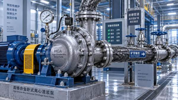
High-chrome white iron is widely used for abrasive slurry components because it provides strong wear resistance in sand and mineral-laden applications.
Rubber-lined components can perform well with fine particles and corrosive service, but may be unsuitable where sharp, large, or angular particles dominate.
Review the expected wear life of impellers, liners, throat bushings, shafts, seals, and discharge elbows. Wear components should be accessible for planned maintenance.
Do not compare pump quotations only by purchase price. A lower-cost pump with frequent liner replacement can produce higher total operating cost over the project duration.
Wear performance also depends on operating point. Running substantially above design velocity can erode wet-end parts and pipelines much faster than expected.
Specify the required material grades, replaceable parts strategy, spare-parts lead time, and field service capability before finalizing the equipment package.
Where river sediment composition is uncertain, include an early inspection interval. Actual wear observations can validate assumptions and guide operational adjustments.
Size the Driver, Controls, and Supporting Equipment
Motor or engine sizing must be based on absorbed power at the expected slurry duty point, including a suitable allowance for variation in solids concentration.
Use the pump power curve and slurry correction data to estimate shaft power. Then account for drivetrain losses, service factor, and site operating conditions.
Electric drives offer efficient speed control and lower local emissions where reliable grid power is available. Diesel drives provide mobility for remote river locations.
Variable-frequency drives can improve control where flow conditions change frequently. They allow operators to adjust speed while avoiding unnecessary throttling losses.
However, speed reduction should still preserve minimum pipeline transport velocity. Reducing speed too far may create settling, blockage, and difficult restart conditions.
Supporting equipment may include cutter heads, suction ladders, jetting systems, screens, booster stations, floating pipelines, instrumentation, and dewatering facilities.
Instrumentation should measure flow, pressure, speed, power, and density where possible. These values help operators identify blockages, wear, cavitation, and inefficient operating conditions.
A well-sized system is easier to control because its operating range remains stable. Controls cannot fully compensate for an incorrect hydraulic design.
Compare Pump Configurations Against Project Constraints
Different river sediment removal projects require different pump configurations. The suitable choice depends on production target, sediment type, access conditions, discharge route, and operating duration.
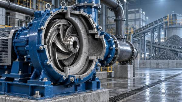
Horizontal slurry pumps are commonly used on dredges and shore-based stations. They can provide high capacity, simplified maintenance access, and flexible drive arrangements.
Submersible slurry pumps are useful for localized removal, confined work areas, deeper pits, or applications where a long suction line would create limitations.
Cutter suction dredges are effective for compacted sand, clay, and dense deposits because the cutter loosens material before it enters the suction system.
Plain suction dredges may be adequate for loose sediment but can struggle with consolidated material. Their production depends heavily on natural sediment mobility.
Booster-equipped systems are appropriate when the pipeline route is long or discharge elevation is substantial. Booster placement requires coordinated hydraulic calculations and controls.
Evaluate mobilization requirements, draft limitations, environmental controls, operator skill, maintenance access, and available power alongside the pump’s nominal hydraulic capacity.
The best configuration is the one that consistently meets the production objective under normal site variability, not the configuration with the largest published capacity.
Use a Structured Technical Evaluation Checklist
A disciplined evaluation process prevents pump selection from becoming a comparison of isolated catalog specifications. Every bidder should receive the same technical design basis.
Provide sediment data, required production, pipeline profile, discharge location, operating hours, water depth, access restrictions, and environmental operating constraints.
Ask each supplier to state the proposed flow, slurry head, line velocity, solids concentration, pump speed, efficiency, absorbed power, and wear-material assumptions.
Require confirmation of free-passage capacity, NPSH suitability, driver rating, pipeline diameter, and expected performance at both new and worn conditions.
Compare lifecycle costs using energy or fuel consumption, replacement parts, maintenance labor, downtime exposure, commissioning support, and spare-parts availability.
Clarify whether quoted performance is guaranteed for water or slurry. A water-only guarantee is not sufficient for a river sediment removal duty.
Where project risk is high, request references from comparable sediment applications. Similar pump size alone is less relevant than comparable solids, distance, and operating conditions.
A site trial or hydraulic verification may be justified for variable sediment. It can prevent costly underperformance after mobilization and pipeline installation.
Conclusion: Select for Stable Production, Not Maximum Nameplate Capacity
Proper dredging pump sizing combines sediment characterization, target production, transport velocity, total dynamic head, suction conditions, wear resistance, and driver capacity.
Technical evaluators should select a system that maintains solids transport and efficient operation across realistic variations in sediment concentration, discharge distance, and component wear.
For a dredging pump for river sediment removal project, documented hydraulic assumptions and slurry-based performance data are more valuable than broad capacity claims.
When reviewing equipment options, assess whether the proposed DHE Slurry Pump configuration can meet the calculated duty point, maintain adequate pipeline velocity, and support the project’s maintenance strategy.
 Sep 14, 2026How slurry pumping solutions can lower unplanned downtimeSlurry Pumping Solutions help manufacturers cut unplanned downtime through smarter pump selection, condition monitoring, wear control, and lifecycle-focused maintenance strategies.
- Sep 13, 2026When mining slurry pumps need thicker wear-resistant componentsMining Slurry Pumps need thicker wear-resistant components when wear rates disrupt planned maintenance. Learn how to select liners, impellers, and materials for reliable uptime.
- Sep 12, 2026What coal washing pumps need to handle dense magnetite mediaCoal Washing Pumps for dense magnetite media: learn how hydraulic design, wear materials, sealing, and suction stability protect pressure, uptime, and coal recovery.
- Sep 11, 2026How dredging pumps maintain output as solids concentration risesDredging Pumps maintain reliable output in high-solids slurry through optimized hydraulics, wear control, stable suction, and pipeline velocity management.


Get a Quote
Please leave your information and email address, and we will contact you as soon as possible.